
IES ConcreteBending User's Guide
Beams
Beams are created in ConcreteBending by setting the drawing mode to "Draw Beams" from the tab and sketching them on top of an existing slab in the model. Beams are used to distribute applied loads to the concrete slab and add stiffness to the model. Beams use the concrete compressive strength (f'c) defined for the project, which can be found in the tab when nothing is selected. Beams that adjoin one another, regardless of orientation, are modeled such that load transfer (shear and moment) occurs between the members (i.e. there are no end release options for beam elements).
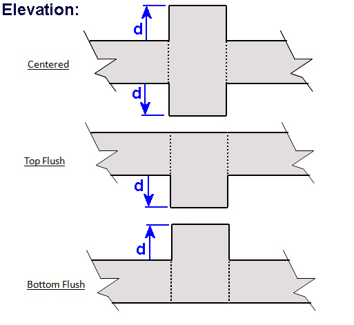
Beams are rectangular in shape and have a specified Beam Width and Projected Depth. All beams have a Vertical Offset Type and Length (defined by the start and end locations).
Vertical forces, in addition moments in two directions can be applied to beams. The self weight of the beam can be included by checking the option for the selected beam in the tab. Beam loads can be entered as distributed evenly along beam length or as the resultant total. Loads can be entered in the global coordinate system or in the beam's local coordinate system (defined as parallel or perpendicular to the beam).
In the finite element model, beams are modeled using member elements in the same plane as the plate elements used to model the slab. The stiffness of each beam is adjusted based on the Vertical Offset setting (i.e. the parallel axis theorem is used to modify the stiffness).
The results from the finite element analysis can be displayed graphically in the Analysis Results view. The tab displays the numerical results that correspond to the colored graphics. With nothing selected, the results displayed in the Project Manager are a summary for the selected result case, whereas if a single beam is selected, the Project Manager shows the result range for the selected beam. The various Result Cases that were included in the finite element analysis can be selected using the Result Case drop down from the tab. Furthermore, moment, shear, and displacement diagrams for each result case can be viewed using the Beam Graph tab. Analysis results can also be reported in tabular form using the Text Reports.
ConcreteBending checks and designs concrete beam members according to specifications listed below.
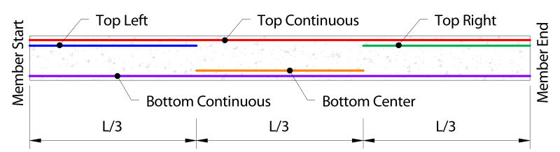
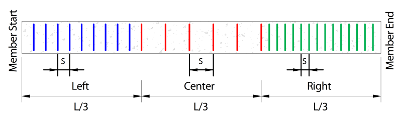
Longitudinal and transverse reinforcing vary along the length of the member, as shown below (respectively).
When designing beams, several parameters must first be defined. These parameters can be set by selecting a beam from the view and using the tab.
| Beam Details |
Specification - The Design Specification used to design the beam. Disable Checks? - Causes selected design group to be omitted from design checks. High Seismic? - (ACI Only, Use Reduced φ Factors for Members Resisting Earthquake Effects) Enabling this parameter lowers the φ factors as indicated by ACI 318 Section 21.2.4 for members that are designed to resist earthquake effects and are part of a structure that relies on special moment resisting frames or special structural walls to resist earthquake effects. ConcreteBending relies solely on this parameter in determining whether or not to use reduced φ factors (it does not attempt to calculate whether the shear capacity is greater than the shear corresponding to the development of the nominal flexural strength of the member). Only shear φ factors are influenced by this parameter for design according to the ACI specification. Overstrength? - Causes the member to be designed using overstrength load combinations. Check Level - Determines the level of detail reported from design checks. Options are: To Failure (Fastest), Each Limit State, and All (Slowest, but provides the most information). Start/End Column Widths - Widths of supporting columns at start and end of beam. These widths are used for determining where critical moment, shear, and torsion are at the ends of the beam. The critical demands are taken at the face of the column since member's effective depth significantly increases once the column is reached. These ends correspond to the member's local axes, where the local x-axis goes from the start-node to the end-node. Note that the critical section for shear can be taken "@ d" from the face of the support using the "Shear "@ d" from start/end" parameter (below). Shear "@ d" from start/end - When enabled, the shear value calculated "@ d from the face" of the support is used for the shear and torsion checks when the check location is between the face of the support and d. Note that when using the CSA design specification, "dv" is used instead of "d". |
| Reinforcement Details |
Use Metric Bars - Should metric reinforcement be used instead of imperial bar sizes? Longitudinal Fy: Specified yield strength of the longitudinal reinforcement in the beam. |
| Top, Bottom, Side (Torsional) Reinforcing |
Top Reinforcement - The size and quantity of Top reinforcement throughout the beam. Bottom Reinforcement - The size and quantity of Bottom reinforcement throughout the beam. Side Reinforcement - The size and quantity of Side reinforcement throughout the beam per each side. Note side bars are not used to resist flexure. |
| Shear Reinforcement |
Fy - Specified yield strength of the stirrups in the beam. Size - The size of transverse reinforcement. Number of Legs - The number of legs used for shear reinforcement. Are Stirrups Closed? - Are closed stirrups used throughout the section? Spacing - The center-to-center spacing of the stirrups. A different stirrup spacing can be specified for each 1/3 of the beam length. A spacing of 0 means no stirrups are provided. |
| Beam Cover |
Top Cover - Concrete clear cover at the top of the section. Calculated as the distance from the top of the stirrup to the top of the section. Bottom Cover - Concrete clear cover at the bottom of the section. Calculated as the distance from the bottom of the stirrup to the bottom of the section. Side Cover - Concrete clear cover at the side of the section. Calculated as the distance from the side of the section to the stirrup. |
Beam results can be viewed graphically in the Design Results view. By default, the controlling unity value is displayed for beams. The unity results for a specific design check (such as the Shear Check, Flexure Check, Torsion Check, etc.) can be viewed by changing the Design Information parameter under the Beam Details category of the tab.
Design results can also be viewed in text form using the Text Reports view. Once on the Text Report tab, a list of available deign tables is shown on the tab and can be added to the text report by double-clicking an individual table or dragging and dropping a table into the report.