Introduction
The script feature in ConcreteBending is a powerful tool used to create models objects, generate service cases, apply loads, extract results, etc. using a command line interface. In addition to supporting the various Commands outlined in this Help File, the command line will accept any valid command in the C# Programming language (allowing the use of if statements, for loops, etc.). In addition to using the command line directly, more complex Scripts can be generated in any text file and read into the program. This allows models with complex geometry to be created, parametric studies to be performed, finite element meshes to be automatically refined until convergence, etc.
Command Line Basics
- Location
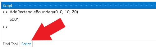
- The Script tool is accessed by selecting the Script tab at the bottom of the Find Tool. By default, the Script will replace the Find Tool when selected, but the two can be floated and docked independently if needed.
- Units
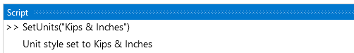
- Input and output are always in the current unit style. The style can be changed from the command line.
- Add Boundaries
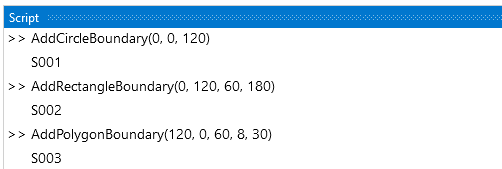
- Add circular, rectangular, or polygon Boundaries of specified sizes and location using the appropriate commands.
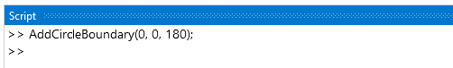
- The return value can be suppressed by using a semi-colon on at the end of the command.
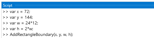
- Information can be stored in variables and math can be performed in the command line. Variables circumvent the need to input the same number repeatedly. The example below uses variables to defined the center coordinates and the width of a rectangular boundary (assuming the current unity style is Kips & Inches). Math is then used in the in the command line to define height of the boundary as two times the width. Note: When storing a value in a variable, the line must end with a semicolon.
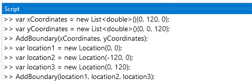
- Boundaries of non-standard shape can be defined based on lists of the X and Y coordinates or based on an array of Locations. Note: Locations can be stored as variables and used to define various items in the model, allowing the items to perfectly coincide.
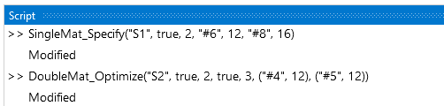
- The slab's reinforcement details (e.g. bar configuration, bar cover, design approach, etc.) can be defined using the various commands.
- Add Point Supports
- Point Supports can be added to the project at specific coordinates or Locations.
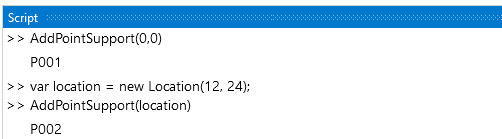
- Point Supports can be renamed if the name that is automatically generated is not satisfactory.
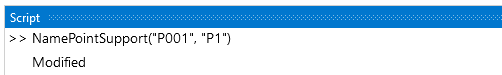
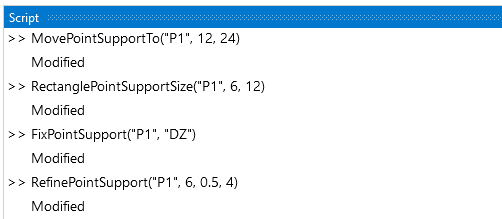
- Once the Point Support is added, it will automatically be selected, and its properties can be modified in the Project Manager as usual. Alternatively, there are various commands to modify the Point Support parameters, see the Commands page for a complete list. Note: Item names must be enclosed in quotes.
- Add Beams/Line Supports
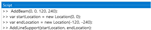
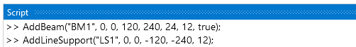
- Beams and Line Supports can be added to the project based on start and end coordinates or locations.
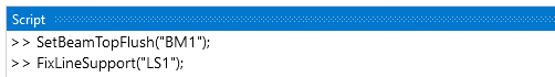
- Various properties can be set when creating Beams or Line Supports.
- A variety of parameters can be modified for existing Beams or Line Supports.
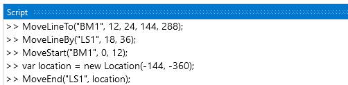
- Beams and walls can be moved using the command line.
- Apply Loads
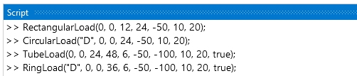
- Rectangular, Circular, Tubular, and Rings loads can be added to the model with various input options (i.e. service case, location, pressure type, etc.). Note: Use a negative magnitude to apply loads in the negative global direction.
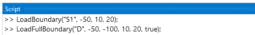
- Individual boundaries or the full boundary can also be loaded using the command line.
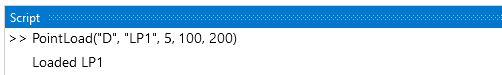
- A variety of options are available to apply loads to Load Points using the command line as outlined on the Commands page. In the example below, Load Point LP1 is loaded in the D service case with a 5 kip vertical force in the Z, a 100 kip-in moment about the X-axis, and a 200 kip-in moment about the Y-axis (assuming the current unity style is Kips & Inches).
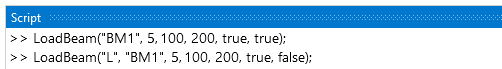
- Beams are loaded using the LoadBeam command which can take various inputs.
- Analysis Settings
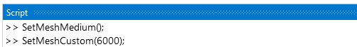
- The command line can be used to set the mesh to a standard value (Coarse, Medium, or Fine) or to a User Defined value.
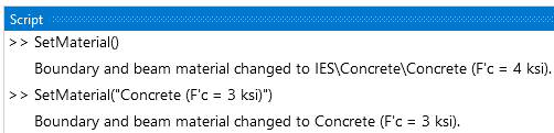
- The SetMaterial() command can be used to set the material for the boundary and beams in the project. This command launches the material dialog box so that a material can be chosen. Alternatively, the name of the material can be used in the command to directly set the material.
- Obtain Results
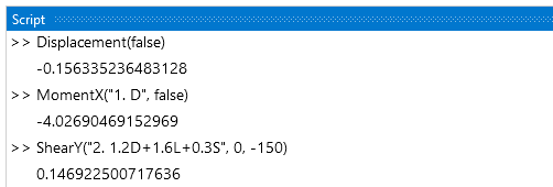
- The maximum or minimum displacement, shear or moment across all result cases or for a specified result case can be obtained using command line. Also, the command line can output the displacement, moment, shear, or bearing pressure at a specific location for a defined result case.
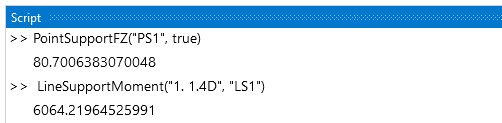
- The maximum or minimum Point Support or Line Support force or moment across all result cases can be obtained using command line. Also, the command line can output the force at a specified Point Support or Line Support Point for a defined result case.
- Miscellaneous
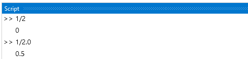
- Integer Math: In the command line, the quotient of two integers is an integer which may not produce the intended result. See the C# Numeric Types Tutorial for more information.
C# Programming
The command line accepts any valid command in the C# Programming Language, allowing the use of if statements, for loops, etc. In the example below, a command is defined to describe the y coordinate of a parabola terms of x. The Pow(Double, Double) method of the .Net System Math Class is used to perform squared operation. A four loop is used to add the x and y coordinates of the boundary to lists which are then used to define the boundary. In addition to using the command line to program directly, more complex Scripts can be generated in any text file and read into the program.

