The Seismic Load module is designed to perform seismic calculations per ASCE 7-16, using Chapters 11 and 12. Below is summary of the user inputs, as well as a discussion of the calculations that are performed.
The seismic load data is saved with the project file (.lhp) and does not persist from project to project as with the dead and live loads.
Data defined on the seismic load tab does not affect any other load tabs within the program.
| Risk Category |
Risk - The structure's risk category as determined from Table 1.5-1 |
|
| Site Information |
Specification - The ASCE 7 specification used for the seismic calculations. Site Class - The classification assigned to the site based on the types of soils present, as defined in Chapter 20. Lat/Long Search - Search for Ss, S1, and TL values using latitude and longitude coordinates. This feature uses the USGS Seismic Design Maps Web Services and the 2016 ASCE 7 Standard End Point. More information on the USGS Web Services can be found at https://earthquake.usgs.gov/ws/ Ss, g - The mapped MCER spectral response acceleration parameter at short periods. S1, g - The mapped MCER spectral response acceleration parameter at a period of 1-second. Long Period Transition, TL - The mapped long-period transition period. Determine SDC from SDs only? - Should the Seismic Design Category be chosen from the SDs value only? The user must verify that the criteria of Section 11.6 is met prior to changing this setting. Override Fa - Should the short-period site coefficient be overridden? Fa Override - The value to use for short-period site coefficient if overridden. Override Fv - Should the long-period site coefficient be overridden? Fv Override - The value to use for long-period site coefficient if overridden. |
|
| Seismic Force Resisting System |
Has Structural Irregularity - Does the structure have an irregularity as defined in Section 12.3.2? Response Coefficient, R - The response modification coefficient for the seismic force resisting system. Deflection Amplification, Cd - The deflection amplification factor for the seismic force resisting system. X, Y, Z Overstrength - The overstrength factor for the seismic force resisting system in the X, Y, and Z-directions. X, Y, Z Redundancy - The redundancy factor for the seismic force resisting system in the X, Y, and Z-directions. |
| Building Information |
Number of stories - The total number of stories in the structure. Building Height - The total height of the structure. (read only) Seismic Weight - The total effective seismic weight of the structure. (read only) |
| Building Heights |
Story 1: Height - The height of the first level within the structure. Story 2: Height - The height of the second level within the structure. etc... |
| Building Weights |
Story 1: Weight - The portion of the total effective seismic weight attributed to the first level. Story 2: Weight - The portion of the total effective seismic weight attributed to the second level. etc... |
|
Approximate Method |
CT - The building period coefficient. x - The building period exponent value. |
For structures not exceeding 12 stories above the base as defined in Section 11.2 where the seismic force-resisting system consists entirely of concrete or steel moment-resisting frames and the average story height is at least 10-ft, equation 12.8-8 may be used to determine the approximate fundamental period.
|
Masonry/Concrete Shear Wall Structures |
Base Area - The area of the base of the structure. Wall sets - The number of shear wall sets within the structure. Each shear wall set should contain one or more walls with the same web area and length. Total shear walls - The total number of shear walls to consider as part of the Cw factor. (read only) Total web area of shear walls - The sum of web areas of all shear walls. (read only) Total length of shear walls - The sum of wall lengths of all shear walls. (read only) |
|
Number of walls PER SET |
Set 1: Number of walls - The number of individual shear walls associated in Set 1. etc... |
|
Shear wall web area PER WALL |
Set 1: Web area per wall - The shear wall web area of each wall in Set 1. For walls with varying web areas, add more Wall Sets. etc... |
|
Shear wall length PER WALL |
Set 1: Length per wall - The shear wall length of each wall in Set 1. For walls with varying length, add more Wall Sets. etc... |
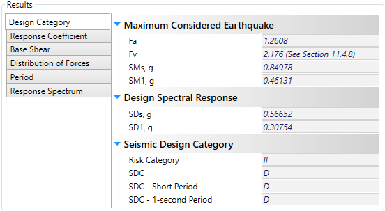
The Design Category tab shows the results of the calculations required to determine the seismic design category of the structure per Section 11.6.

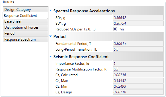
The Response Coefficient tab shows the results of the calculations required to determine the seismic response coefficient, Cs, per Section 12.8.1.1.

The Base Shear tab shows the results of the calculations required to determine the seismic base shear, V, per Section 12.8.1.

The Distribution of Forces tab shows the results of the calculations required to determine the vertical distribution of seismic forces per Section 12.8.3.

The Period tab shows the results of the calculations required to determine the approximate fundamental period of the structure, per Section 12.8.2.1. If the Period calculation method was set to 'User Entered', the entered value will be shown here for convenience.

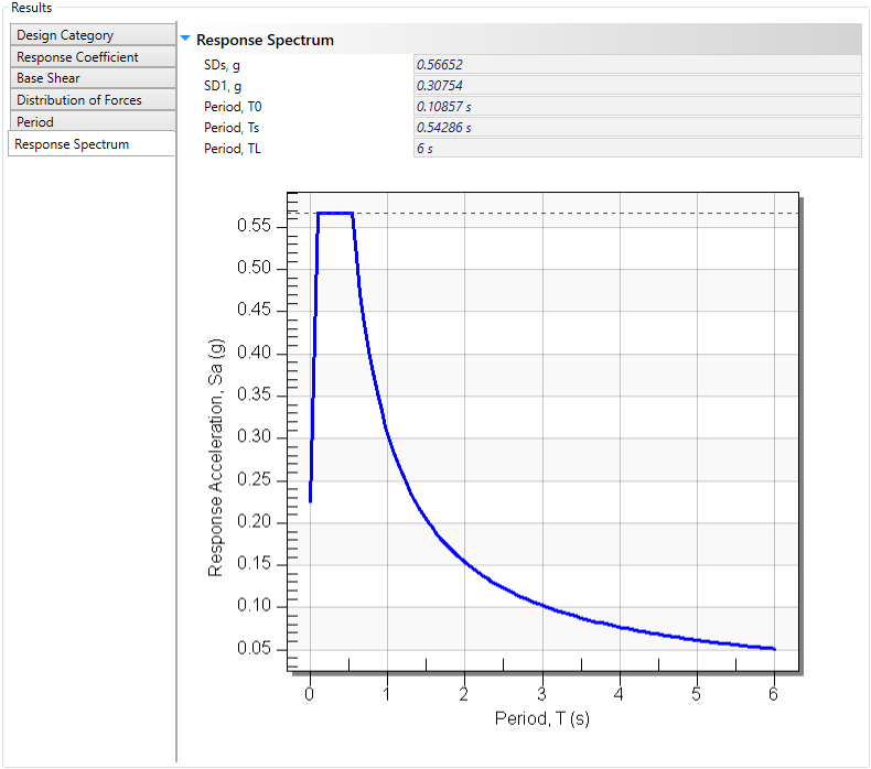
The Response Spectrum tab shows the results of the calculations required to generate the design response spectrum, per Section 11.4.6.
