Finite element analysis is used to determine the torsion properties and the shear stresses for the shape. Mesh refinement is required to get accurate results. The analysis runs automatically in the background and you do not need to wait for analysis to finish when editing your shape.
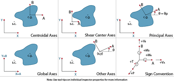
The tab in (when the Analysis View is active) allows input for the applied loading on the section, the location of the applied loading (body forces), a mesh refinement adjustment, and a selector to determine which of the available results to display in the graphic window. Shown in the figure below are the orientations and positive sign convention for the applied loads on the section.

The location of the applied load is specified in the drop down box. The options here include: the Global Axes (X,Y), the Centroidal Axes (x,y), the Principal Axes (1,2,theta), Shear Center, and Other Axes. If Other Axes is chosen, you will need to specify the X and Y coordinates (in the global system) of the origin of your coordinate system as well as the angle of rotation. The location you specify can cause implicit eccentricity as described below.
| Load |
Description |
| Axial Force, P | An applied axial force, where compression is negative, tension is positive. If the load is applied at a point other than the centroid, it will also induce moments on the cross section. |
| Bending Moments, Ma, Mb | Moment sign conventions are defined in the figure above. |
| Shear Force, Va, Vb | Positive shear is in the direction of the positive axis. Shear forces applied at a point other than the shear center will induce torsion as well. |
| Torque, T | Applied torsional moment, counterclockwise is positive, following the right-hand-rule. |
Loads are applied as body forces not concentrated forces. Since they are applied as body forces, stress concentrations are not considered.
The mesh refinement slider is used to control how many elements are used in the analysis. You can compare the results between different meshes to determine if the results are "converging" on the true elasticity solution. Finite element analysis is inherently approximate. To ensure your analysis results are accurate you should follow a mesh refinement technique, which is outlined below. The goal is to get accurate results, while minimizing the time you spend waiting for results. Generally, you use a coarse mesh to get fast preliminary results, and then use finer meshes for final results.
You may select among the following for graphical results in the tab:
| Result View |
Description |
| Flattened Model | Shows how ShapeBuilder merged touching parts, removed overlaps, and subtracted holes. The model shown is used for analysis. |
| Mesh | Displays the finite element mesh used to run the analysis. You might look at this to judge element sizes, to find meshing problems or issues (you may zoom and pan the view). |
| Normal Stress, σz | Total normal (Z-direction) stress, from combined axial and bending. |
| St. Venant, τxz | X-direction St. Venant shear stress as a result of applied or incidental torsion. |
| St. Venant, τyz | Y-direction St. Venant shear stress as a result of applied or incidental torsion |
| Warping Function | Warping normal function |
| Flexural, τxz | X-direction flexural shear stress from applied shear. |
| Flexural, τyz | Y-direction flexural shear stress from applied shear. |
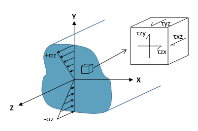
| Combined, τxz | X-direction total shear stress found by combining flexural and torsional shear stresses. Sign of the stress is used in the combination and the sign convention is shown in the figure below. |
| Combined, τyz | Y-direction total shear stress found by combining flexural and torsional shear stresses. Sign of the stress is used in the combination and the sign convention is shown in the figure below. |
| Resultant, τ | Total Resultant Shear Stress found by taking the square root of the square of the total stresses. It is a positive number. The resultant represents the vector resultant value. |
The orientation and sign convention of the resulting stresses is shown below. All stresses shown are positive; note that a normal stress in tension is designated as positive. ShapeBuilder reports only the shear stresses on the Z face of the cube below.
