Using a CAD program, create a .dxf or .dwg file of the cross-section you would like to Import into ShapeBuilder. The section should be composed of Polyline, 2D Polyline, 3D Polyline, Circle, Ellipse, 3D Face, or Solid objects.
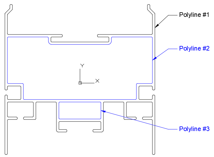
In the figure below, Polyline #1 is the shape outline and Polyline #2 and #3 are contained inside of #1 and will be turned into Holes within ShapeBuilder.

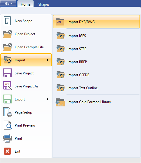
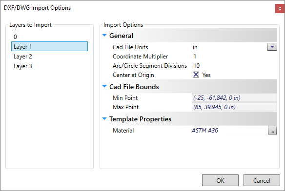
From the File menu, select and browse to the file created in Step 1. This will bring up the DXF/DWG Import Options dialog, where you can select the Layers to Import and set other miscellaneous options for the import process. Once everything is set properly, select OK to Import the file. Note: Tool tips provide additional information by hovering your mouse over each field, including the Layers available to import. The Material field defaults to the User Preference 'Default Parametric Material' setting.
 |
 |
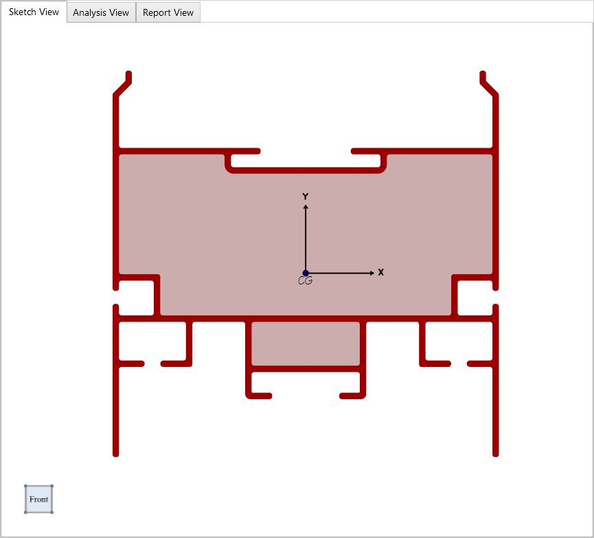
The image below shows the resulting shape that has been Imported into ShapeBuilder.
