Simple section properties are calculated for the overall shape and displayed in the tab. When the shape is composed of multiple parts, some of the individual part properties are also shown in the tab. Selecting one part causes more of that part's properties to appear, in the tab. For shapes that include multiple materials, the "base" material can be specified. The properties for the composite shape are then transformed with a modular ratio. A single asterisk (*) indicates that transformed properties use a modular ratio of n = E/E_base. A double asterisk (**) indicates that transformed properties use a modular ratio of n = Fy/Fy_base (when a material has multiple values for Fy, the minimum value is used in the modular ratio). For example, areas of each part are weighted by the modular ratio of n = E/E base as shown in the equation below.

| Depth |
Overall maximum dimension in the Y-direction. |
| Width | Overall maximum dimension in the X-direction. |
| Perimeter | The distance around the boundary of the shape. If holes overlap the outer perimeter to form a notch, it is the "flattened" perimeter that is calculated. Switch to the Analysis View to see the flattened shape. |
| Weight | Weight per unit-length of the net section, if it were extruded out of plane. |
| Ebase | Base modulus of elasticity. Used in calculations having transformed properties (n = E/E_base). |
| Fy_base | Base yield stress. Used in calculations having transformed properties (n = Fy/F_base) |
| Area |
Gross or full cross-sectional area of the shape, less the area of any holes. |
| Moments of Inertia, Ix, Iy |
Also know as the second moment of the area. A measure of the stiffness of the cross-section and its ability to resist bending moments. |
| Product of Inertia, Ixy |
The product of inertia is zero when the x-y axes are the principle axis and is defined by the following equation: |
| Radius of Gyration, rx, ry |
Radius of gyration is the distance from a reference axis to a point at which the entire area may be concentrated and still have the same moment of inertia as the distributed area. It is used as a measure of the stability of a column.
|
| Section Modulus, Sx+, Sx-, Sy+, Sy- |
The section modulus is useful for calculating the extreme bending stress where I is the moment of inertia about the axis in question and c is the distance from the centroid to the extreme fiber. The plus (+) and minus (-) signs indicate the direction of c from the centroid. For example, Sx+ is the section modulus about the x-axis in the positive y direction. |
| Center of Gravity, Xc, Yc |
Also known as the Centroid of Area. The point where the moment of the area is zero about any axis as defined below, where the terms x̄ and ȳ represent the moment arms for the centroid of the differential element that is used. This point is measured from the global XY axes and is labeled CG in the Sketch View. |
| Principal Axes Angle, α |
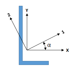
The axes orientation at which the maximum and minimum moments of inertia are obtained, positive according to the right-hand rule. This is the system on which all flexure formulas are based. Moment of inertia Ixy is zero with respect to this coordinate system. Alpha is the angle of rotation from ShapeBuilder's geometric (X-Y) axes to the principal axes (see the figure below). |
| Major & Minor Moments of Inertia, I1, I2 |
The maximum (I1) and minimum (I2) moments of inertia defined on the principal coordinate system axes (see the figure below). The product of inertia with respect to these axes is always zero. |

| Polar Moment of Inertia, Ip |
Moment of inertia with respect to the z-axis (normal to the section plane). This is equivalent to the torsion constant, J, for circular cross-sections only. In other cases, the polar moment of inertia is larger (perhaps much larger) than the torsion constant. |
| Polar Radius of Gyration, rp |
The polar radius of gyration about the centroid of the shape. |
| Plastic Modulus, Zx, Zy |
The plastic section modulus is the arithmetical sum of the statical moments about the plastic neutral axis of the parts of the section above and below that axis. This term is used to calculate the plastic moment capacity of a section Mpx = σy*Zx, where σy is the yield stress of the material. When a section is composed of multiple materials of differing yield stresses, the Zx and Zy values are calculated by weighting each part with its yield stress referenced to Fy_base. |
| Plastic Neutral Axis, Xpna, Ypna |
The plastic neutral axis is located such that the equation below is true. If the section is composed of multiple materials of differing yield stresses, the Fy_comp and Fy_tens values may vary across the cross-section. If the section is composed of only one material, the PNA divides the area of the section into equal halves and is not always located at the centroid.
|
| Area |
Gross or full cross-sectional area of the part, less the area of any holes. |
| Major & Minor Moments of Inertia, I1, I2 |
The maximum (I1) and minimum (I2) moment of inertia of the part about its principal axis (see the figure above). |
| Center of Gravity, Xc, Yc |
The distance from the part's centroid to the global origin.
|