
IES VisualAnalysis User's Guide
Cable Elements
Cable elements sag and are unique due to their initial displacement. Cable elements only carry axial loads (they do not carry shear or bending moments). Cables tend to exhibit highly geometrical nonlinear behavior and are highly sensitive to their initial conditions. Cables have a number of uses including suspension and cable stayed bridges, guyed poles and towers.
Cables can be created using the command to draw members on a Grid or to existing nodes in the model. After cables are created, they can be selected to specify the Catenary Length, Diameter, Material, and Connecting nodes in the tab. If the specified Catenary Length is longer then the Straight Length, a value for the Initial Sag for the cable will be displayed. If the specified Catenary Length is shorter than the Straight Length, the cable will be prestressed and the prestressing force can be calculated using Hooke's law. Cables can be Split, Copied, Moved, or Rotated using the commands in the Structure ribbon.
Cables can only be loaded with concentrated nodal loads. Therefore, cables must be split before a concentrated load is to be applied along the span. Cable elements only carry axial loads (they do not carry shear or bending moments). Note: the Y global axis is always considered the vertical axis for cables which is important as it defines the cable's sag.
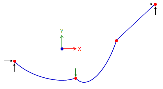
Cables are split using the Structure | Split Cable command. There are three options for splitting cables: equal catenary segments, equal horizontal projections, and custom catenary segments. For the equal catenary segments and equal horizontal projections options, simply specify the number of segments. For the custom catenary segments option, specify the number of segments and the length of each segment (except for the last segment) as measured along the cable. The length of the last segment will automatically calculated as the remaining portion of the cable's length. It is recommended that cables be split after the geometry is fully defined. While VisualAnalysis does allow segments of a cable to be edited after it is split, there is no "knowledge" of its global identity. In other words, a cable segment could sag within the overall cable as shown below (this does not make physical sense and should be avoided).
Since cables are geometrically nonlinear, the cable element stiffness is a function of the tension in the element, and the solution method is iterative, it is possible to apply too large a load to a cable element and not have the analysis converge. In this case, simply reduce the load and VisualAnalysis will automatically reanalyze. When experiencing convergence issues, consider exploring the Advanced Analysis Project Settings in the tab. Specifically, the Return Unconverged Results feature can be used to display partially converged results within the analysis results. If an analysis is unable to converge, it is possible that a partial solution (i.e. reduced loads) is able to converge, for which results can be displayed. Note: mode shapes cannot be obtain for cables (or for other nonlinear problems) in VisualAnalysis.
The axial force, axial stress, and displacements can be displayed for cables in the Results View. Select one or more cables to see the extreme results in the tab or select the Result Type on the tab to be displayed graphically. The analysis results for cables can be reported by inserting the Cable Results table from the tab. Also, the Cables table can be reported to include the parameters (diameter, material, straight length, catenary length, etc.) for each cable in the model.
An upward arc type displacement is sometimes seen in long cables that have been split into several sub cables when large displacement magnifiers are used in the tab. Set the to Absolute and the to a value of one to see the true deflected shape.