
IES VisualAnalysis User's Guide
Concrete Wall/Slab Design
VisualAnalysis designs reinforced concrete walls/slabs to resist shear and pure bending (the effects of axial forces are not considered for design) according to the following design specifications:
Walls/slabs are analyzed and designed using finite element plate/shell elements that have either 3 or 4 nodes. Individual plate elements can be drawn in the Model View or plates can be automatically generated for Areas that are drawn in the Model View. Plate element can be grouped together in Design Meshes to reduce the required amount of data entry and simplify the design of a structure. All of the plates in a Design Mesh must have the same parameters and a Design Mesh cannot contain a mix of manual plates and automatically generated plates. If the "Auto-Mesh Plates?" setting is enabled in the tab, Design Meshes are created automatically for plates with similar parameters (material, orientation, thickness, etc.). Alternatively, design meshes can be created or modified manually.
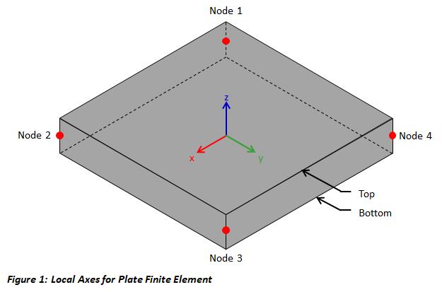
Plate elements for walls/slabs have a local coordinate system which is used when defining the rebar for the design mesh. The local x-direction and y-direction are in the plane of the plate and the z-direction is normal to the plate according to the right-hand-rule as shown in Figure 1. The top of the plate is defined in the +z-direction while the bottom of the plate is defined in the -z-direction (top and bottom are used to define reinforcement mats, rebar cover, exposure classifications, etc.). The local axes for individual plates can be displayed in the Model View while the local axes for the Design Mesh can be displayed in the Design View.
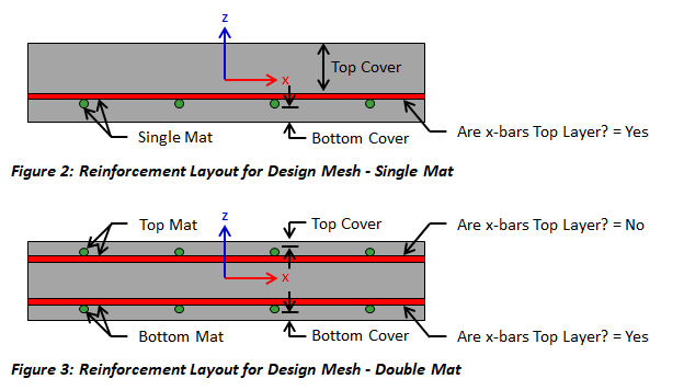
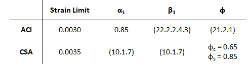
The wall/slab reinforcement is specified for each design mesh. Therefore, design meshes should be created for each region where the size and/or spacing of the reinforcement will change. Rebar is oriented with the local coordinate system for the Design Mesh. Using the "Direction of x-bars" feature in the tab, the local x-axis for the Design Mesh are aligned with a global coordinate or custom direction. Rebar is specified as a bar size and spacing for each bar layer in each direction (the minimum steel requirements are checked according to the selected design specification). The "Are x-bars Top Layer?" feature can be used to specify which layer of reinforcement in mat is closest to the top of the of the wall/slab(see Figure 2 & 3). The location with rebar through the thickness of the wall/slab is set by adjusting the values for the top and bottom cover. While a single mat of reinforcement only has two layers of steel (local x-bar and local y-bars), a double mat has the following four layers:
VisualAnalysis uses strain compatibility, equilibrium, the elastic-perfectly plastic constitutive law for steel, and the Whitney rectangular stress distribution for concrete to determine the flexural capacity of concrete plate elements. In determining the capacity of a wall/slab, the ACI and CSA design specifications use slightly different values for the maximum concrete compression strain, the ratio of average stress in the rectangular compression block to the specified concrete strength (α1), the ratio of depth of rectangular compression block to depth to the neutral axis (β1), and the strength reduction factor (φ). The following table shows the values for these limits or provides the applicable code reference.
Slabs/walls that experience two-way action have both bending moments (Mx and My) and twisting moments (Mxy). The twisting moments may cause the maximum bending demand to not coincide with the X or Y reinforcing directions. To ensure that the slab/wall has adequate strength in all directions, VisualAnalysis uses the method by Wood and Armer as explained by MacGregor and Wight1,2 to design the reinforcement. The following equations are used to calculate the design moments which are obtained from Wood and Armer when k=1.0. According to MacGregor and Wight,2 k=1.0 is the best choice for a wide range of moment values.
Mx+ = Mx + |Mxy| ≥ 0
Mx- = Mx - |Mxy| ≤ 0
My+ = My + |Mxy| ≥ 0
My- = My - |Mxy| ≤ 0
VisualAnaysis designs walls/slabs for shear where the effects of axial load are not considered. The shear capacity for each plate in the design mesh is checked and the maximum unity value is reported for the mesh. While, VisualAnalysis checks one-way shear for the concrete plate elements in the local x-direction and y-direction, punching shear is not considered in the design (to design for punching shear, use ConcreteBending or VisualFoundation). For the CSA A23.3 design specification, the β parameter for shear design is determined using value for special member types (β = 0.21) when the plate thickness does not exceed 350 mm. Otherwise, the Simplified Method is used to determine β according to the design specification.
Several parameters must be defined to design a concrete wall/slab in VisualAnalysis. The design parameters are set in the tab when the Design View is selected. After creating a Design Mesh, choose one of the plates that belongs to the group in the Design View to set up the Design Mesh's Parameters. Since the design parameters apply to all plates in the Design Mesh, it is often best to choose the most conservative condition that applies to any member in the mesh.
| Concrete |
Mesh Name - Specify the name of the design mesh Plates - Total number of plates in the mesh and the names of the plates f'c - The 28-day concrete compressive strength (modify this value in the Model View) Thickness - The thickness of the wall/slab (modify this value in the Model View) Specification: The Design Specification used to design the plates in the Design Mesh. High Seismic? - (ACI Only, Use Reduced φ Factors for Members Resisting Earthquake Effects) Enabling this parameter lowers the φ factors as indicated by ACI 318 Section 21.2.4 for members that are designed to resist earthquake effects and are part of a structure that relies on special moment resisting frames or special structural walls to resist earthquake effects. VisualAnalysis relies solely on this parameter in determining whether or not to use reduced φ factors (it does not attempt to calculate whether the shear capacity is greater than the shear corresponding to the development of the nominal flexural strength of the member). Only shear φ factors are influenced by this parameter for design according to the ACI specification. Overstrength? - Causes the Design Mesh to be designed using overstrength load combinations. |
| Minimum Steel |
Min Steel Ratio - Select which criteria should be used for minimum steel ratio (shrinkage & temperature, walls, user specified, or none). Min Steel for Flexure - Should the minimum steel ratio in the code reference be used for the flexural reinforcement that is in tension in the model? Max Spacing Limits - Select which criteria should be used for the maximum reinforcement spacing limits (one-way slab, two-way slab, walls, none). Min. Steel Placement - Select where the minimum steel should be placed in the wall/slab (all steel in top, all steel in bottom, split steel between top & bottom, or use the minimum steel requirement for both the top and bottom). Are x-bars Vertical? - Specify the orientation of the x-bars. This parameter is used for the wall minimum steel calculations. |
| Reinforcement (General) |
Use Metric Bars - Should metric reinforcement be used instead of imperial bar sizes? Steel Fy - Yield stress for the longitudinal reinforcement in the wall/slab Direction of x-bars - Specify the direction for the x-bars in the global coordinate system Bar Configuration - Double Mat (two layers) or Single Mat (single layer) Top/Bottom Cover: Clear distance to outer bars from face of the wall/slab |
| Reinforcement (Single or Top/Bottom Mat) |
X/Y Size - Rebar size for this mat and direction X/Y Spacing - Rebar on center spacing for bars in this mat and direction Are x-bars Top Layer? - Are the x-direction bars the top layer (local +z side) of the mat? |
| Environmental Structures |
Top Exposure - Exposure classification for the top (local +z) side of the wall/slab Bottom Exposure - Exposure classification for the bottom (local -z) side of the wall/slab Has Movement Joints? - Does the slab have movement joints? If so, specify the joint spacing |
To achieve an adequate design, the Design Mesh's Parameters can be manually adjusted until all the design checks pass. Alternatively, the built in optimization feature in VisualAnalysis can be used to iterate through some of the parameters to find an adequate solution using the following process:
1. Create the Wall/Slab
In the Model View draw areas or plates to create the walls/slabs.
2. Support and Load the Walls/Slabs
Define support conditions for the model and apply the service level loads to the elements. Set the strength design load combinations in the Load Case Manager.
3. Specify Preliminary Parameters
Set the preliminary thickness and material properties (note: concrete walls/plates in a design group must have the same thickness and material properties).
4. Analysis and Preliminary Design
VisualAnalysis will automatically analyze the model and perform the appropriate design checks. Simply click on the Results View tab to view the analysis results for the model or the Design View tab to see the design results. VisualAnalysis uses default parameters for concrete wall/slab reinforcement.
5. Create/Modify Design Meshes
VisualAnalysis will automatically create meshes for elements based on material, orientation, length, and/or thickness. Alternatively, Design Meshes can be created or modified manually using the options in the Design Ribbon.
6. Concrete & Minimum Steel Parameters
For each Design Mesh, select the appropriate design specification, overstrength parameters, minimum steel requirements etc. in the in the tab in the Design View.
7. Define Reinforcement (General)
Specify the general reinforcement parameters (bar type, steel Fy, Direction of x-bars, bar configuration, and cover) in the tab in the Design View.
8. Design the Mesh (Optimize Slab Reinforcement)
After selecting a Design Mesh, click the Design the Mesh button in the Design ribbon. In the Optimize Slab Reinforcement dialog box, choose which layers of reinforcement are to be optimized and set the reinforcement range and bar spacing limits (note: each layer can be optimized individually if the parameters need to be different for each layer). Click the Optimize Now button to search for the optimal bar and size and spacing for each layer of reinforcement that was chosen. Upon clicking "Done" the reinforcement parameters for the design mesh are updated with the optimized reinforcement. VisualAnalysis automatically re-calculates the unity values for each element based on the new reinforcement parameters. Since the Design the Mesh feature does not influence the wall/slab thickness or concrete strength (i.e. the stiffness of the slab does not change) the design does not need to be synchronized (as is the case when using the Design the Group feature for members). Since the Design the Mesh feature does not significantly change the reinforcement depth, it is not an effective tool to design for shear. Therefore, the thickness and/or strength of the concrete should be adjusted manually in the Model View until the shear checks pass before optimizing the reinforcement for flexure.
11. Verify Unity Ratios
The final step in the design process is to verify that Unity Ratios in the Design View are less than the Unity Success Limit and to ensure that no errors or warnings are present in the model.
Double-clicking on a Design Mesh in the Design View will generate a report for the plate elements in the mesh. Results for every plate element can be shown, which may produce lengthy reports, or only the controlling results can be displayed using the Extreme Rows parameter in the tab. Report can include the input parameters, the design details, and the code checks showing demand, capacity, intermediate values, and unity check results. A design specification reference is provided for each unity check and any errors or warnings for the Design Mesh are included in the report.