
IES VisualAnalysis User's Guide
Deflections
Deflections are checked for load combinations that have been marked as "Deflection" or "Allowable and Deflection "in the Load Case Manager.
You must choose the method for checking deflections! For cantilevered beams you generally need to check "total" deflection (described below). Depending on how your model is constructed (e.g. combined members or separate member-elements), or how members are grouped together, you may need to change the type of displacement check! The measured displacements can change dramatically (and even reverse direction!) depending on the method chosen.
You may specify a limit based on a span ratio (like L/360), or a specified displacement limit (like 0.25 inches). The span ratio approach allows you to group members that may not have the same span length, yet still provide a consistent deflection limit. You may disable specific limits by setting a zero value (for a displacement limit) or a small value (for a span-ratio limit).
The span-length is calculated as the member-element length, or for a combined member it is the total length--regardless of the types of internal connections or supports! Span-ratio checks may not make sense for combined members that are supported in their interior. Span-ratio checks generally do not work for cantilevered members.
Relative Member vs. Total Deflection
You will also need to choose between two methods of measuring the actual deflection. VisualAnalysis uses the terms "Member" and "Total" to distinguish between bending deflection in a member element and the total movement of a member including the nodal displacements.
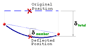
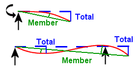
In the picture on the right above, the member deflections are calculated from the green-line between the deflected end-points to the red-line (the deflected beam), while the total deflections are calculated from the dashed-blue line.
In many cases, the member and total displacements will be identical. This is true for a simple span beam, or (approximately) a beam framing between two columns. In the case of a beam split into multiple elements you will need to make sure that you are checking a total displacement. In the case of a beam spanning between two girders, and the girders are also deflecting, then you will want to check member displacements for this beam. Finally in some situations you will simply need to check absolute displacements that you have pre-calculated. Using the span-ratio limits does not work for all situations in modeling, though it is most convenient for typical beams.
You can view deflection categories in the , on the combinations page for any load combinations marked for "Deflection" or "Allowable and Deflection" checks. See loading for design for more details.
You can specify different deflection limits for each category in a Design Group's parameters.
VisualAnalysis does not directly check drift requirements. There are special Reports available to show building or member drift that you may use to check your drift requirements and make frame-wide adjustments as necessary. The "Complete Member" report item will display the actual drift extremes calculated for a column member.