IES VisualAnalysis User's Guide
Effective Length Factors
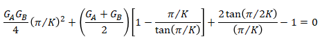
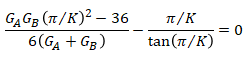
VisualAnalysis calculates the effect length factors for members in sidesway inhibited frames (i.e., braced frames) and in sidesway uninhibited frames (i.e., sway frames) using the equations below that are provided in the Appendix 7 Commentary of the AISC 360-16 design specification.1
Braced Frames
Sway Frames
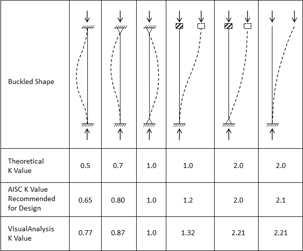
In the equations above, the A and B subscripts refer to the joints at the ends of the column. When calculating G, VisualAnalysis sums the members that are rigidly connect to the joint, are perpendicular to the column, and are in the plane for which buckling of the column is being considered. Note: Members framing into a joint that are not parallel to the column’s local y or z axes are not accounted for when calculating G. If needed, the Kz and Ky factors can be manually overridden to account for sloped members that frame into a joint. According to the AISC design specification, G is theoretically infinity for pinned end supports but can be taken as 10 for practical designs of column ends supported by but not rigidly connected a footing or foundation.1 VisualAnalysis conservatively assumes G = 50 for the pinned condition which returns K factors slightly more conservative than those recommended for design by AISC as shown in the image below. For the fixed end condition, VisualAnalysis assumes G = 1.0 which represents a column end rigidly attached to a properly designed footing. The image below shows the theoretical K values, the AISC recommended design K values, and K values produced by VisualAnalysis for columns with idealized boundary conditions.