IES VisualAnalysis User's Guide
Member Loads
Member loads are applied to selected members using the command or the Ctrl+2 hotkey. In the Add Member Load(s) dialog box, the Load Case, Load Type, Magnitude and Location are specified.
The following Load Types are available for members:
Concentrated and distributed loads can be applied with respect to the local or global coordinate system. Directions are distinguished with coordinate letters {X, Y, or Z} for global coordinates and {x, y, or z} for local coordinates. The local axes and corresponding loads can be reversed using the command or the sign of the magnitude can reverse the action of the load in the local or global coordinate systems. Member loads are always assumed to pass through the centroid or shear center of the member. Distributed loads can be applied to the projected length of a member, which is typical for applying snow loads to a sloped roof.
Member loads are located from the starting node (Node 1) of the member using an offset along the length. For distributed loads, both the starting offset and the ending offset are measured from Node 1. There is an On Full Span option which specifies that the distributed load converse the entire span from Node 1 to Node 2. Multiple distributed loads may be applied on a single member, but cannot overlap.
VisualAnalysis has two features for generating multiple point loads across members at once. Select either Fractional Span Points or Evenly Spaced Points to generate multiple concentrated loads on each member. Fractional loads can be placed randomly (they work well for placing loads at say 1/3 points of members with different span lengths). Use the evenly spaced option to create loads a fixed distance apart. Although the multiple point loads are generated in a single step, they immediately become independent concentrated loads for editing or deleting.
Eccentric loads cannot be applied to a member in VisualAnalysis. All member loads pass through the centroid or shear center to cause no secondary effects. Both the load and the associated moment must be applied manually can account for load eccentricity in the model.
The Ice Weight for members in VisualAnalysis is calculated according to the ASCE 7-22 provisions. When a Service Case has a Dead (Ice) load Source, the Ice Weight Load Type becomes available in the Add Members Load(s) dialog box. VisualAnalysis can automatically calculate the design ice thickness for the member based on the specified nominal ice thickness, the height factor, and the topographic factor (wind parameters must be defined for the ice service case). Alternatively, the design ice thickness can be manually specified in the program. The diameter of the smallest circle that would contain the shape's cross-section and the design ice thickness is used to determine the cross-sectional area of ice. A conservative value of 56 pcf is used for the ice density to determine the magnitude of the uniform load in VisualAnalyisis. Ice weights always act in the project's vertical direction.
When a Wind Load Case is selected, the Wind (+ Ice Area) Load Type is available in the Add Members Load(s) dialog box. The load case wide wind parameters and the project wide IBC wind parameters are specified in the Service Case dialog box.
VisualAnalysis calculates the wind velocity pressure, qz, according to the ASCE 7-22 provisions. The velocity pressure is a function of various parameters specified in the wind Service Case. Wind (+ Ice Area) loads are applied as constant uniform loads over the length of the member where the average height of the member is used to determine the wind velocity pressure.
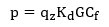
The design wind pressure, p, can be manually specified or VisualAnalysis can automatically calculate the member design wind pressure according to the ASCE 7-22 provisions as follows:
Where:
qz = Velocity pressure per ASCE 7-22
Kd = Wind directionality factor
G = Gust factor
Cf = Force coefficient
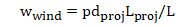
The gust factor, G, is specified under the project wide IBC wind settings and the wind directionality factor, Kd, is specified in the wind parameters. By default, the force coefficient, Cf, is determined according to the ASCE Substation Structure Design Guide and the aspect ratio correction factor, c, is used to modify the force coefficient as discussed in the design guide.1 The Cf value can be manually overridden to use values from ASCE 7-22 for various types of structures. The design wind pressure is used to determine the design wind uniform load for members which is calculated as follows:
Where:
p = design wind pressure
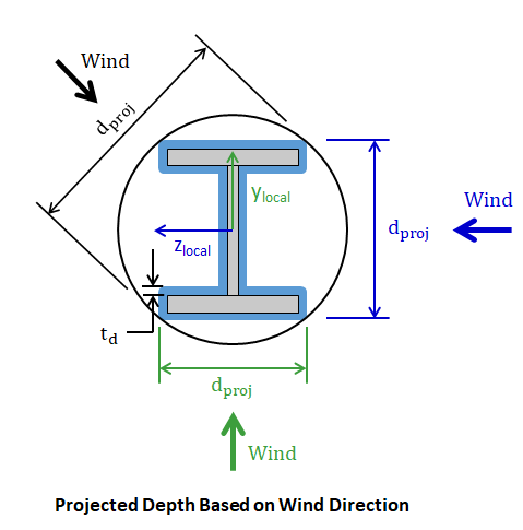
dproj = The projected depth of the member's cross-section including the design ice thickness, td (see image below)
Lproj = Projected length of member in the plane normal to the wind's direction (note: the length reduces as the orientation of the member becomes closer to parallel to the wind direction)
L = Length of member
Note: The projected depth, dproj, depends on the direction of wind as shown in the image below. When the direction of the wind aligns with one of the members local coordinate axes, the projected depth of the shape including the design ice thickness is used in the calculation. When the direction of the wind does not alight with one of the member's local coordinate axes, the projected depth is conservatively taken as the smallest diameter a circle that can circumscribe the member's cross-section including the design ice thickness. VisualAnalysis can automatically calculate the design ice thickness for the member based on the specified nominal ice thickness, the height factor, and the topographic factor. Alternatively, the design ice thickness can be manually specified in the program.