IES VisualAnalysis User's Guide
Moving Loads
Moving Loads are an analysis feature to model truck loads on bridges or crane loads on girders. These loads can move along the length of the members in either the positive x-direction or in both directions when defined to be reversible. This tool eliminates the need to create multiple load cases to simulate moving loads and provides intelligent reporting capabilities. Two pre-defined truck loads (the AASHTO HS 20 Short and the AASHTO HS 20 Long) are provided by default and custom truck and lane loads can be created.
Custom Trucks can be created, modified, or deleted using the . For each truck, provide a name, define the magnitude and offsets for the axels, and set the magnitude of the lane load. Custom Trucks are saved in the Truck.xml Custom Data File in the folder and can be used in different VisualAnalysis projects.
Moving load are created using the Create Moving Load button on the Advanced tab of the Load Case Manager. In the Moving Load Case dialog, define the Name, select the Truck, specify if the load is Reversible, and set the Require Axis Match parameter. Next, select the members that will carry the moving load (note: members selected in the model view will automatically be selected in the Moving Load Case dialog). For a moving load to be applied to multiple members, the members must form a valid chain.
Moving Load cases can be modified by selecting the load graphically in the Model View or in the tab. Once selected, the parameters for the moving load will appear in the tab.
The Moving Load feature works by creating and analyzing a series of load cases in the background that place the truck loads at incremental distances starting at one end of the member and moving across to the other end. The number of points where the load is placed along each member is determined by the number of Load Stepping Points parameter defined in the Advanced Analysis section of the tab. Increasing this number may yield more precise results, but will also increase the size of your project file, slow the performance of the analysis, and increase the output in reports. Note: A nonlinear model will preclude the use of moving loads since the analysis relies on superposition, which is invalid for nonlinear models.
Moving Load Cases results are presented in Extreme Min. and Extreme Max. envelope. Moving Load Cases can also be combined with results from any other type of load case using Result Superposition. The Moving Load results also offer Influence Diagrams for nodes or members a specified points in the model.
When a Moving Load Case is analyzed, the influence diagrams is automatically created for the member(s) and the Influence Diagram window tab will appear. Influence Diagrams are available for any node or member in the structure. Select the member or node in the Model View and switch to the Influence Diagram window to view the diagram for the selected item. With the Influence Diagram window selected, define the Graph Details parameters in the tab. For members, adjust the Offset to see the influence diagram at various locations along the member.
Influence lines represent the effect of the moving load on a particular point in the model as the load moves. Influence diagrams are constructed for a positive (upward Global Y) 1 kip point load. The vertical axis shows the magnitude of the result in question when the 1 kip load is applied, while the horizontal axis shows the position of the 1 kip load along the member chain. The typical use for these influence diagrams is to determine where to place other (perhaps non-moving) loads to achieve a maximum affect at some point in the structure. The moving load analysis does this automatically for the moving truck loads and lane loads, but this tool can be used to determine where to positioned loads in another load case.
To obtained design check for the results of moving loads, a Result Superposition case must be created in the tab and the appropriate Design Category must be specified.
Members subject to moving load are reported similar to members applied with other standard loads. Report tables, such as Member Forces, Member Stresses, etc. work are available for moving load cases . A table to report the Moving Loads that have been defined is also available.
The results presented for moving load cases are envelope results. To find where the truck was when a given force or moment occurred in a member include the corresponding "When" column (Fx When, Vy When, Mz When, etc.) in the report. The "When" columns can be added from the Columns to Display section of the tab. Note: The "When" report column does not return a location if the truck consists of only a lane load (i.e. the truck has no axels).
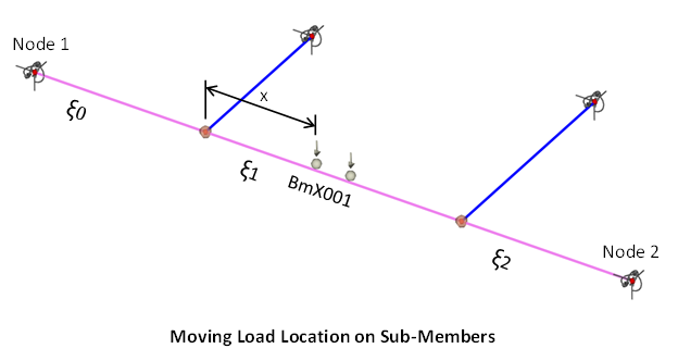
Members with intermediate connected nodes are converted into separate sub-members for the finite element analysis (FEA). The greek letter ξ is used to indicate which sub-member has the results while the location indicates where the moving load is on the sub-member (the start of the sub-member is closest to Node 1 of the main member). For example, member BmX001 in the figure below has two members framing into it with two connected nodes. Therefore, member BmX001 with the moving load is broken into three sub-members for analysis (ξ0, ξ1, ξ2) where ξ0 is the sub-member closest to Node 1 of the main member. In the figure, the load is moving from Node 1 to Node 2 and is located “On BmX001ξ1 @ x ft”.