
IES VisualAnalysis User's Guide
Semi-Rigid Connections
Semi-rigid connection behavior can be specified for the strong bending (Rz) and/or weak bending (Ry) at the ends of a member elements. The other degrees of freedom (Dx, Dy, Dz, Rx) are always controlled by member end releases and are defined as either rigid or released. While steel connections are typically idealized as Rigid (Fully Restrained Moment Connections) or Simple (Simple Shear Connections) they actually behave somewhere in between these two extremes (i.e. rigid connections have some flexibility and simple connections provide some moment restraint). Also, some connections are semi rigid (e.g. for a partially restrained moment connection). In either case, Semi-Rigid connections can be used to model these connections in VisualAnalysis.
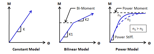
Semi-Rigid connections are specified by selecting a member and setting the parameters in the Semi Rigid section of the tab. Three different models can be used for Rz and Ry of Node1 and Node 2 of a member in VisualAnalysis: Constant, Bilinear, and Power Model. The Constant model is defined by the slope of the moment-rotation curve (K). The Bilinear model is defined by the initial slope (K1), the final slope (K2), and the transition moment (Bi-Moment). The Power Model is defined by the shape factor for the fit of the curve (n), the initial rigidity of the connection or slope of the first linear portion of the moment-rotation curve (Power Stiff.), and the ultimate moment capacity (Power Moment) for the connection that will be asymptotically approached. For the Power Model, the larger the value of n, the steeper the curve and the closer it "fits" the two tangents.
There are a number of references that address semi-rigid behavior. For example, Stability Design of Semi-Rigid Frames gives formulas and tables for specific connections and their associated rigidity values.1 Also, Modeling of Connections in the Analysis of Thin-Walled Space Frames is a useful reference. 2
Both the Bilinear and Power Model can be used to model plastic hinge behavior. If the plastic hinge does not occur at the end of a member, the member will need to be split so that a semi-rigid connection can be specified at the hinge location. In some situations, manual iteration might be required to determine hinge locations and split and insert the hinges. Note: The hinge locations could be different for each load case or combination.
The rigidity model selected for semi-rigid behavior of the connection will designate whether a linear or a nonlinear analysis is performed. The Constant model uses a linear analysis while the Bilinear and Power Models both require a nonlinear analysis.
For each specified semi-rigid connection the report specifies: