IES VisualAnalysis User's Guide
Example: Unbalanced Snow Loads
When analyzing snow loads, ASCE 7 states that balanced and unbalanced snow loads shall be analyzed separately. Below is an example outlining the use of Patterned Service Cases for separating the balanced and unbalanced loading conditions within VisualAnalysis.
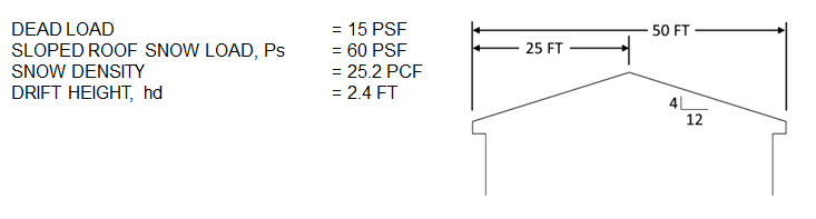
Determine analysis results for the roof rafters using ASCE 7 ASD load combinations for balanced and unbalanced snow loading conditions. Assume rafters are spaced at 24-inches o.c.

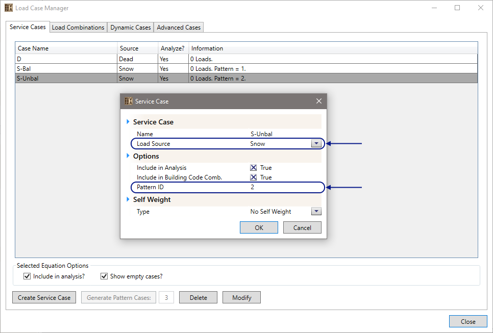
Create two or more new service cases through the Load Case Manager. The first Service Case, named S-Bal, has a Snow load source and a Pattern ID = 1. The second service case, named S-Unbal, has a Snow load source and a Pattern ID = 2. This will allow loads placed in these service cases to be automatically separated in the Building Code combinations and will be analyzed separately.
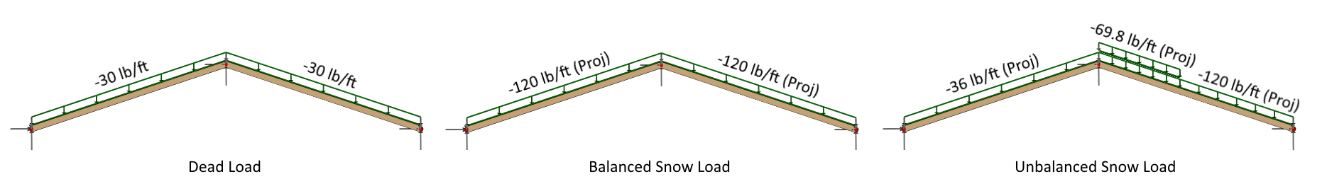
A simple two-member model is created, and boundary conditions applied. The dead loads are applied to the model in the ‘D’ Service Case. Balanced snow loads are applied in the ‘S-Bal’ Service Case. Unbalanced snow loads are applied in the ‘S-Unbal’ Service Case.
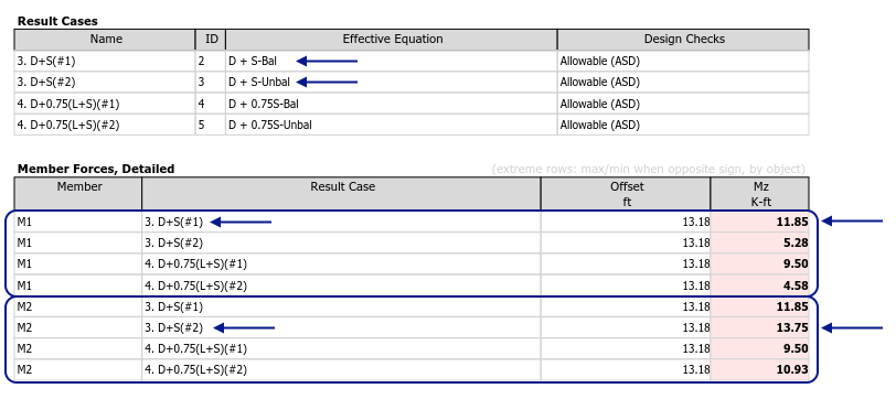
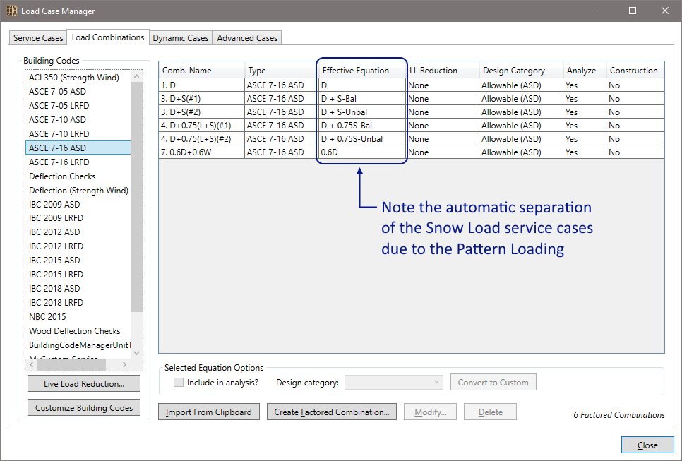
Within the tab, select an ASCE 7 ASD building code to auto generate load combinations. Note that equations using ‘S-Bal’ and ‘S-Unbal’ are automatically separated into combinations without the other present.
From the Results View tab, graphically review the analysis results by changing the Result Case drop down from the Ribbon. A Summary of the Result Case is available in the Project Manager when nothing is selected. The individual member results can be viewed in the Project Manager by graphically selecting the member.
A text report displaying the analysis results can be generated using the Report View tab. The tables below summarize the extreme strong axis moment within both members.