IES VisualAnalysis User's Guide
Understanding Analysis
VisualAnalysis uses the Finite Element Analysis (FEA) method. While the inner workings of the FEA numerical procedure in VisualAnalysis are beyond the scope of this help file, this section offers practical guidelines for applying the method.
Use the command to check the model and ensure that it is ready for analysis. The Model Check information is displayed in the Report View. For the analysis to be preformed, the model must follow the guidelines listed below.
A Statics Check is performed for each load case analyzed in VisualAnalysis. The total applied loads in each global direction is calculated and compared to the sum of all support reactions in the corresponding global directions. The applied loads are based on the deformed shape of the structure while the reactions are based on the structure's undeformed shape. If the loads and reaction are equal and opposite in magnitude, then the structure is in equilibrium. An imbalance indicates that the deflections are large enough to generate inaccurate results which might indicate that there is a modeling problem. VisualAnalysis provides a warning if a significant imbalance is detected. If a warning is received, carefully review the model to ensure it is set up correctly and verify the results. The Statics Check is displayed on the tab or the Statics Check Information table can be added to the report.
Check to see if displacements and stress-levels in the model are reasonable and expected. A large force imbalance, either in percentage or in absolute value is a problem that cannot be ignored. Errors are usually caused by large displacements or rotations which can result from global or localized problems.
If the statics imbalance is found in a first-order analysis, perform a second-order (P-Delta) analysis to see if the imbalance decreases. If the imbalance does not change or gets worse consider supporting the structure more or reducing the applied loads.
When a first order analysis is performed in VisualAanalyis, it is assumed that the deformation of the structure is not large enough to severely affect equilibrium. When a second order (P-delta) analysis is performed, however, the analysis includes secondary effects resulting from geometric stiffening or softening in the structure. Typically, compression softens a structure and tension stiffens a structure. In general, P-delta analysis are only valid for small to moderate displacements. VisualAnalysis does not use finite elements that can handle large displacements, therefore if the displacements appear large they should be carefully reviewed as the FEA results may differ from the real-world behavior. VisualAnalysis tries to detects large displacements and produce a warning, however, the definition of a large displacement is somewhat arbitrary. Structures with misapplied loads or incorrectly entered geometric or material properties can produce results with large displacements. Also, large displacements can arise if unreasonable preliminary sizes are used for members or plates. The Statics Check, as discussed above, will indicate if the equilibrium of the structure is not satisfied due to large displacements and if the results should be questioned.
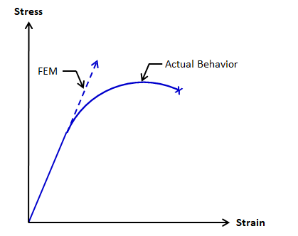
Materials in VisualAnalysis are assumed to be linear, elastic, and isotropic. It is possible for elements in the model to have stresses that exceed the yielding, cracking, crushing, buckling, etc. capacity in reality. While VisualAnalysis provides some checks against abnormally large stresses, it is important to verify that the element forces and stresses are within reasonable limits. If the elements in the model are allowed to exceed the stress where material nonlinearity occurs, the model can produce results that are stiffer than reality as shown in the figure below.