Requires: IES VAConnect
Requires: Advanced Level
VAConnect is a connection design program that can assist with the design of steel base plates and their anchorage, simple beam shear connections and various beam moment connections per AISC requirements. VisualAnalysis's integration with VAConnect can save a tremendous amount of time because it exports forces from many load cases and multiple joints, saving you all the bookkeeping required to manually set up the connection's loading and geometric parameters.
How to Use IES VAConnect
- Enable Connection Design in the Project settings and turn on the Auto Group Cxns feature. You may customize these.
- Define Result Type in project settings: VAConnect can use service case results or "pre-factored" results.
- Go to Load Case Manager and turn on the analysis for all necessary load cases (they may not be enabled for service cases).
- Use the Filter while in the Design View to display connection graphics. Click on the connection to view properties.
- With a Connection Group selected, launch VAConnect from the tab.
General Requirements & Limitations
- Steel materials and shapes only
- Grouped connections must be 'identical' in type, shape, orientations, etc.
- Only LRFD load combinations are supported
Available Connection Types
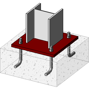
Base Plate + Anchorage
|
|
Limitations
- Base plate is assumed to be perpendicular to the member's local axis
- A single member framing into a supported node or with spring-supports (no braces may frame into this node)
- Permitted shapes: WF-Shapes, HSS (rectangular tubes), Pipes, and Rectangular or Round Columns
- Torsional column reactions are not considered.
|
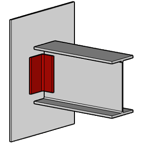
Double Angle Welded
|
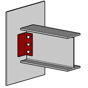
Double Angle Welded Bolted
|
|
Limitations
- Beam is nearly perpendicular to the support
- A single member framing into a support column or girder
- Permitted beam shapes: WF-Shapes, Channels
- Permitted supporting member shapes: WF-Shapes, Channels, HSS, Pipe, Rectangle or Round
- Only shear force from the beam will be transferred to VAConnect
|
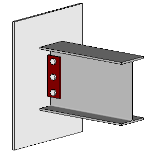
Shear Tab
|
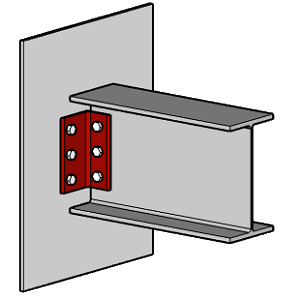
Double Angle Bolted
|
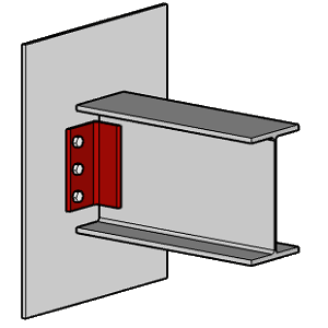
Double Angle Bolted Welded
|
|
Limitations
- Beam is nearly perpendicular to the support
- A single member framing into a support column or girder
- Permitted beam shapes: WF-Shapes, Channels
- Permitted supporting member shapes: WF-Shapes, Channels, HSS, Pipe, Rectangle or Round
- Only shear and axial forces from the beam will be transferred to VAConnect
|
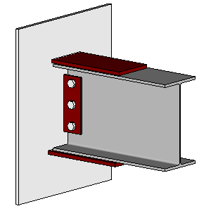
Welded Flange Plate
|
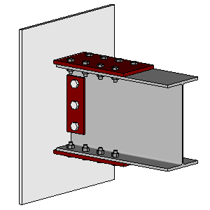
Bolted Flange Plate
|
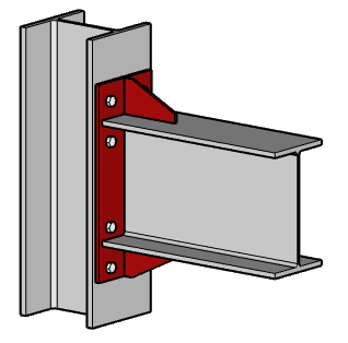
Bolted End Plate
|
|
Limitations
- Permitted beam shapes: WF-Shapes
- Permitted supporting member shapes: WF-Shapes, Channels, HSS, Pipe, or Rectangle
- Beam is nearly perpendicular to the support
- A single member framing into the support
|
Limitations
- Permitted beam shapes: WF-Shapes
- Permitted supporting member shapes: WF-Shapes, Channels, HSS, Pipe, or Rectangle
- Beam is nearly perpendicular to the support
- A single member framing into the support
|
Limitations
- Permitted beam shapes: WF-Shapes
- Permitted supporting member shapes: WF-Shapes
- Beam is perpendicular to the support and framing into the flange
- The support flange width must be greater than or equal to the beam flange width
- A single beam is framing into the support column
- Only shear and moment forces from the beam will be transferred to VAConnect (i.e. no axial force)
|
Notes
- The preferred approach is to export service-case results. While you may export “factored” results into VAConnect, which would go in as “prefactored” loads. This is not the best way to design a connection. Use the type in .
- The coordinate systems are different between VisualAnalysis and VAConnect.
- Member local forces in VisualAnalysis are exported to VAConnect, transformed into the appropriate directions.
- Once the project is created in VAConnect it is not “updated” from VisualAnalysis, and no geometric information transfers back to VisualAnalysis.
- If your forces change in VisualAnalysis you must start the process over or manually update the VAConnect project.
- VAConnect reports are only available in VisualAnalysis 'per session'. If you exit and restart VisualAnalysis any VAConnect reports are no longer present.
- No connection data input into VAConnect is currently stored or transferred back to VisualAnalysis.
- You may save VAConnect project files manually to store your input-data and settings for each connection design.
Troubleshooting
If you have problems launching VAConnect from within VisualAnalysis, check the following:
- Uninstall any older versions of VAConnect (2.0 or 1.0) and VisualAnalysis (prior to 12.0), from Control Panel
- Check the "File Associations" on one of the example projects that ship with VAConnect
- Re-install the latest versions of VisualAnalysis and then VAConnect


