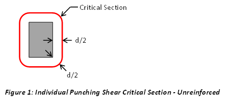
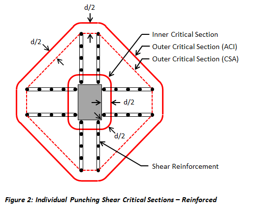
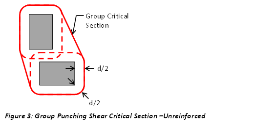
Punching (two-way) shear checks are performed at locations where concentrated loads are introduced into the foundation slab, such as at piles, column piers, and walls. VisualFoundation is capable of checking unreinforced punching shear for individual objects (Figure 1), reinforced punching shear for individual objects (Figure 2), and unreinforced group punching shear (Figure 3). For the design to pass, the strength of the critical section must exceed the net load acting inside the of the section.
The design check for punching shear involves calculating the Critical Section around the object(s), which may be truncated by the slab boundary. The Critical Section is positioned so that the perimeter (bo) is minimized but is not located closer than d/2 to the edges or corners of the object(s), as illustrated in Figures 1, 2, and 3. When punching reinforcement is provided, the design check is performed on both the Inner and Outer Critical Sections (Figure 2). Note: When the CSA design specification is selected, the Outer Critical Section does not extend d/2 beyond the punching reinforcement, as limited by Clause 13.3.7.4.
If a Grade Beam crosses an object's Critical Section, punching shear checks are not performed for that object, and it is excluded from group punching shear. In this case, it is assumed that the Grade Beam will be designed to handle the required shear demands. Note: "-N.A.-" will appear in the punching shear report for any objects excluded from the punching shear check. Furthermore, if a Grade Beam crosses the outer perimeter of an object with punching reinforcement, only punching at the Inner Critical Section is checked. Note: Punching shear checks are also not performed for loads applied directly onto the foundation (e.g., rectangular, circular, tubular, or ring loads).
The Critical Section can be shown graphically in the Foundation Design view. When punching reinforcement is present, the Outer Critical Section is displayed graphically for the object with reinforcement only when punching at the Outer Critical Section controls over punching at the Inner Critical Section.
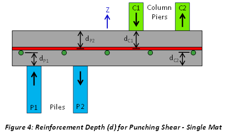
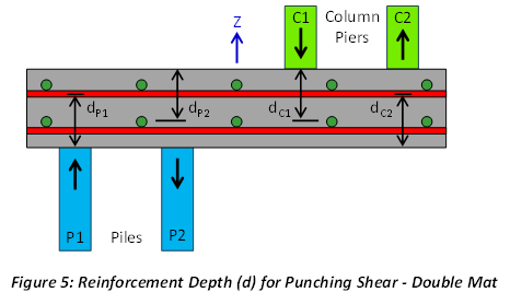
The Reinforcement Depth (d) used in the punching shear calculation is dependent on the load direction. For loads on the slab in the positive Z-direction (e.g., piles in compression, piers in tension, and walls in tension), d is measured from the bottom of the slab. For loads on the slab in the negative Z-direction (e.g., piles in tension, piers in compression, and walls in compression), d is measured from the top of the slab. In VisualFoundation, d is measured to the center of the bars in the reinforcement mat that minimize its value (i.e., the size and orientation of the bars in the mat affect the value of d). Figures 4 and 5 provide examples of how d is calculated for piles and column piers in both tension and compression, for single and double mat bar configurations, respectively. Note: Since VisualFoundation does not design the reinforcement between the various objects (piles, piers, walls, etc.) and the foundation slab, the user must determine if the critical sections for punching of objects in tension are valid.
When the Specify design approach is used for the slab’s reinforcement, d is calculated based on the specified reinforcement bar diameters. When the Optimize design approach is used, d is calculated for each plate element within the critical section using the suggested reinforcement for the design, and the minimum value is used for the punching shear calculation.
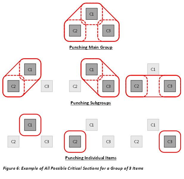
When Piles, Piers, and Walls are closer to each other than the thickness of the slab, VisualFoundation combines them to form a punching shear group. These groups expand to include any additional elements within their boundary (e.g., if an item falls within the reentrant corner of a punching shear group, it will be incorporated into the group). For the group punching design check to pass, the strength of the group's critical section must exceed the net load acting inside of the group's critical section. To include walls in the automatically generated punching design groups, the Include Walls in Groups parameter must be enabled and the Wall Aspect Ratio must be set. Walls with a length/thickness ratio greater than the value specified will not be included in punching shear groups. Walls with large aspect ratios are unlikely to punch and may create undesirable groups.
Group critical sections can be shown graphically in the Foundation Design view. Although the group critical section cannot be directly overridden or modified, adjusting the Override Perimeter Offset parameter (see below) for an individual object within the punching shear group will affect the overall critical section for the group.
When a group contains more than two objects, the punching behavior of a sub-group may govern the design, rather than the behavior of the entire group or the individual elements within it (see Figure 6). For the subgroup punching design check to pass, the strength of the subgroup punching perimeter must exceed the net load acting within the subgroup perimeter. To account for this, enable the Check Subgroups parameter and set the Max Group Size parameter. Note: Groups with more items than the specified number will not be checked for subgroup punching.
The number of subgroups checked grows exponentially, following the equation 2^n - n - 2. For example, a group of 3 objects will have 2^3 - 3 - 2 = subgroups (in addition to 1 main group and 3 individual objects), and a group of 4 objects will have 2^4 - 4 - 2 = 10 subgroups (plus 1 main group and 4 individual objects), etc. Due to the exponential increase in computational cost as the group size grows, the Max Group Size parameter is capped at 10. This ensures that the user does not request a problem that exceeds realistic computational time limits.
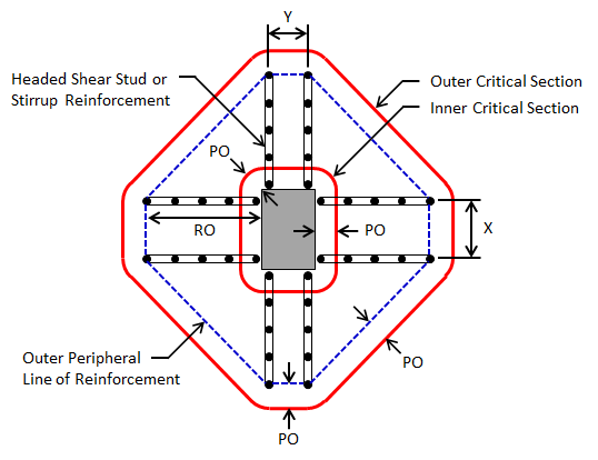
Two-way shear reinforcement can be defined for individual Piers or Column Piles in the form of headed shear studs or shear stirrups. When punching reinforcement is provided, a design check is performed on both the Inner and Outer Critical Sections. The slab's capacity at the Inner Critical Section is calculated as the sum of the concrete and steel reinforcement capacities, while the slab's capacity at the Outer Critical Section is determined based solely on the concrete capacity. Note: The controlling critical section is displayed graphically in the view.
Note: The punching shear reinforcement is assumed to extend away from the object in the Global +X, +Y, -X, and -Y directions, regardless of the object's shape or orientation. If a foundation edge (either an outside edge or hole edge) is located within the Reinforcement Offset distance (see below), the reinforcement is assumed to extend only to the edge of the foundation in that direction.
Below are the group punching shear design parameters. These parameters can be found from the tab.
| Group Punching Shear | |
| Include Walls in Groups? | Do you want to include walls in group punching shear? - Choosing 'Yes' allows you to set the Wall Aspect Ratio parameter. Walls with a length/thickness ratio greater than specified will not be included in punching shear groups. Walls with large aspect ratios are unlikely to punch and may create undesirable groups. |
| Check Subgroup Punching? | Do you want to check subgroup punching? - Choosing 'Yes' allows you to set the Max Group Size parameter. Punching groups containing more items than specified will not be checked for subgroup punching. Increasing this number incurs an exponential computational cost. |
Below are the punching shear design parameters available for an individual Pile or Pier object. These parameters can be found from the tab when a Pile or Pier is selected.
| Piers & Piles Without Reinforcement | |
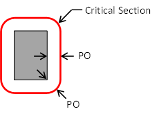
| Override Punching Offset (PO)? | Do you want to override the punching perimeter offset? - Choosing 'No' results in using the slab reinforcement depth (d/2) for the offset. Choosing 'Yes' allows you to enter your own value to be used as the punching perimeter offset. |
 |
|
| Piers & Piles With Reinforcement | |
| Override Punching Offset (PO)? | Do you want to override the punching perimeter offset? - Choosing 'No' results in using the slab reinforcement depth (d/2) for the offset. Choosing 'Yes' allows you to enter your own value to be used as the punching perimeter offset. |
| Are Headed Studs? | Is the reinforcement headed shear studs? |
| Fyt | The yield stress of the reinforcement. |
| Av total | The total area of shear reinforcement around a peripheral line of reinforcement. |
| Spacing | The spacing of peripheral lines of shear reinforcement. |
| X Reinf. Group Width (X) | The width of the stud/stirrup reinforcement group oriented in the Global X-Direction. Enter 0.0 for a single stud rail or stirrup leg line. |
| Y Reinf. Group Width (Y) | The width of the stud/stirrup reinforcement group oriented in the Global Y-Direction. Enter 0.0 for a single stud rail or stirrup leg line. |
| Reinforcement Offset (RO) | The distance from the object face that the shear reinforcement extends outward. |
 |
|