The base plate connection consists of a steel plate that is welded to the base of a column and anchored to a concrete slab or pedestal. The connection resists the reactions from the column including the axial force, shear forces, and moments.
Design Considerations
- Steel base plates and anchorage subjected to applied axial forces and overturning moments are analyzed according to AISC Design Guide 1 (DG1) or with a finite element analysis.
- Base plate design checks for flexure are performed per AISC 360-22.
- Concrete bearing design checks are performed per ACI 318-19.
- Anchorage design checks for shear and tensions demands are performed per ACI 318-19 Chapter 17. Anchorage design is not available when the connection is analyzed using finite element analysis because ACI design provisions assume a rigid plate connects the anchors.
- Anchorage breakout areas for both shear and tension can be graphically displayed.
- Anchorage breakout checks can be suppressed when reinforcing is provided to prevent breakout.
Limit States
VAConnect checks the following limit states for Base Plates (refer to the program’s detailed reports for code references):
- Concrete bearing
- Steel plate bending
- Base plate detailing
- Bolt minimum edge distances for the steel plate
- Bolt tension
- Single anchor tension breakout
- Anchor group tension breakout
- Tension pullout
- Single anchor side blowout
- Anchor group side blowout
- Bolt shear
- Anchor group shear breakout (cases 1, 2 & 3)
- Single anchor shear pryout
- Anchor group shear pryout
- Anchorage tension and shear interaction
- Anchorage detailing
Limitations
- Permitted shapes: I-Beams, HSS (rectangular tubes), Pipes, and Rectangular or Round Columns
- Base plate is assumed to be perpendicular to the member's local axis
- Limited to a single member framing into the plate (i.e. braces may connect to the base plate)
- If analyzing with the DG1 method, all of the limitations of DG1 apply to the base plate program, notably:
- DG1 does not support biaxial bending in the plate
- DG1 does not support the case of an applied axial tension and applied moment
- Only one row of anchors is allowed around the four sides of the base plate
- DG1 simplifies the base plate analysis into essentially a one-dimensional problem (engineering judgment is required to determine when this simplifying assumption is appropriate)
- Please refer to DG1 for further information
- The column-to-base-plate weld is not checked
- Only bending design checks are made on the plate (bolt bearing, block shear, and other steel connection checks are not considered)
- The anchorage design checks do not support post-installed anchors
- The overstrength option (ACI 318-19 Section 17.10.3.4.3d) is used for seismic design for both shear and tension. Also, the tension capacity is reduced per 17.10.5.4. Therefore, the user must to define omega in the project criteria to considering seismic effects.
- The provisions of ACI 318-19 Section 17.7.2.1 (c) and (d), concerning shear parallel to an edge and shear at a corner, are not checked (these checks can be manually performed, by applying the correct load towards the edge)
- Torsional column reactions are not considered in the analysis or design
- Biaxial shear anchorage interaction is not supported
Finite Element Analysis
As an alternative to DG1, finite element analysis can be used to find the critical plate bending moment and concrete bearing pressure. Finite element analysis removes the loading and one-way bending limitations of DG1 (see above). Finite element analysis and DG1 are built on entirely different assumptions about the base plate connection’s behavior (for example, DG1 assumes the plate is rigid). Results from the two analysis methods will often differ significantly.
The base plate is modeled using plate elements. Very stiff plate elements are used in the region of the plate under the column. One-way elastic springs model the concrete and anchorage. The user must define the stiffness of the concrete support and the anchor bolts. The mesh element size must be adjusted until the bearing and bending unity values converge. A significant amount of engineering judgment is required for a successful analysis. Information on the element formulation used and a discussion of mesh refinement can be found in the VisualAnalysis Help File.
The bending moment used for plate design is calculated by taking the extreme principal stress times the plate’s section modulus. The bending demand can spike near the corners of wide-flange and rectangular columns. Users are given the option of ignoring these spikes by disregarding the demands within a specified distance from these corners. To view the model and results in detail, export the FEA model to VisualAnalysis.
Anchorage design checks are not performed when FEA is used since ACI’s assumption of a rigid plate may not be satisfied.
Shear Breakout Groups and Load Distribution
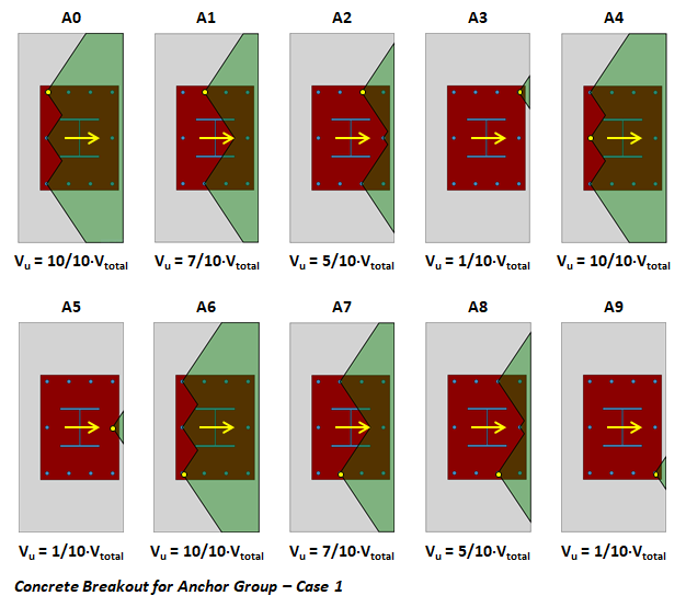
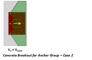
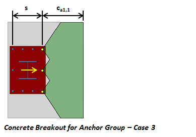
Various load distributions must be considered when designing anchors for shear demands. This process is described by Figure R17.7.2.1b of ACI 318-19 chapter 17. The figure describes three cases that must be considered when designing for shear breakout. The logic behind the commentary cases, which involves only two anchors, leads to many possible breakout cases when the group has multiple anchors. VAConnect's anchorage design checks take the following approach:
- A breakout group is considered for each anchor in the connection. The shear force carried by each group is taken as the total shear demand times the ratio of the anchors in the breakout group to the total number of anchors in the connection (see the figure below). The shear limit states of bolt shear and pryout are checked for each breakout group. VAConnect can graphically display the breakout group for each anchor.

- If the anchors are welded to the steel plate (as specified by the user), only the breakout group starting from the back row of anchors (Case 2) is considered as discussed in ACI 318-19 Section 17.7.2.1.

- If the overall anchor spacing (s) is less than the edge distance to the near-edge anchors (ca1,1) as shown in the following figure, then the failure surfaces may merge and Case 3 is conservatively used for the strength of the breakout group (see ACI 318-19 Section 17.7.2.1). It should be noted that Case 3 is also applicable if the base plate holes are such that front row of anchors take the majority of the load before the rest of the anchors are engaged (see Example 8 of ACI 355.3R-11 page 76 for further discussion of when this more severe load distribution may exist). VAConnect, however, does not considered Case 3 based on the bolt hole condition.

Bolt Shear and Load Distribution
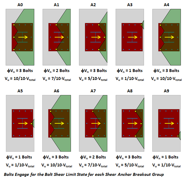
When the anchors near the free edge start to form a failure cone due to concrete breakout the load will redistribute to the stiffer rear anchors as explained in ACI 318-19 R17.7.2.1. Therefore, VAConnect only uses the anchors farthest from the edge (on the perimeter of the breakout group) for the bolt shear limit state (see Example 10 of ACI 355.3R-11 particularly page 92). The figure below shows the demand and the number of bolts that resist shear for the breakout group associated with each anchor. The bolt shear unity value (Vu/φVn) is conservatively taken as the maximum unity value of all the cases for bolt shear regardless of which breakout case controls.

Anchorage Interaction
The anchorage design checks consider the interaction of tension and shear forces per ACI 318-19 Section 17.8. The design checks, however, do not consider the interaction of biaxial shear forces in two perpendicular directions. In the case of a connection subjected to shear forces in the X and Y directions (Vx and Vy) and a tension force (T), the interaction check will consider Vx combined with T and Vy combined with T, separately. The combination of Vx, Vy, and T is not considered by the program because there is no guidance provided by the ACI 318-19 specification. Therefore, this particular design check is left to the discretion of the user.


