A Welded Flange Plate connection consists of two steel plates that are welded to both the support and the flanges of the beam to resist moment. VAConnect assumes that the Welded Flange Plate connections possess sufficient rigidity to maintain the angles between the connected members and behave as fully restrained moment connections as discussed in the AISC Steel Construction Manual Part 12. While various simple shear connections can be used in conjunction with welded flange plates, VAConnect uses a shear tab to resist the applied shear loads.
Welded Flange Plate connections are checked per the AISC 360-22 design specification. VAConnect allows the flange plates to be connected to the support with either a double sided fillet weld or a complete-joint-penetration groove weld. The capacity of the complete-joint-penetration groove welds are not checked since the strength of the joint is controlled by the base metal according to AISC 360-22 Table J2.5. The length of the weld at the support can be manually set to a value less than the width of the flange plate, which is needed for cases when the flange plate is wider than the support. Fillet weld are used to connect the flange plates to the flanges of the beam. The end weld (i.e. the weld along the back edge of the flange plate perpendicular to the beam's span) can be enabled or disabled. When the end weld is disabled, the weld group is two parallel lines and when enabled the weld group is a U-shape. To avoid overhead welding in the field, the top flange plate is typically narrower than the beam's top flange (with an end weld) while the bottom flange plate is typically wider than the beam's bottom flange without an end weld. To allow enough room for placement of the fillet welds, VAConnect requires the difference between the width of the flange plate and the width of the beam's flange to be greater than or equal to two times the size of the weld.
Shear is transferred from the web of the beam to the support through the shear tab connection. Since the angle between the beam and the support in a fully restrained moment connection remains unchanged under loading, eccentricity is neglected when checking limit states pertaining to the shear tab.3 To satisfy equilibrium, the moment from the eccentric shear force (eccentricity · Fv) is added to the moment applied to the connection (Mz). The axial force is assumed to be distributed uniformly to the flanges of the beams (the shear tab connection is therefore assumed to have negligible axial stiffness compared to the flange plate connections). The moment at the connection is resolved into an effective tension-compression couple acting as axial forces at the beam flanges. Finally, the forces in the flanges plates can be calculated as R = (Mz + eccentricity · Fv) / d ± Fa/2.
VAConnect checks the following limit states for Welded Flange Plates (refer to the program’s detailed reports for specific code references):
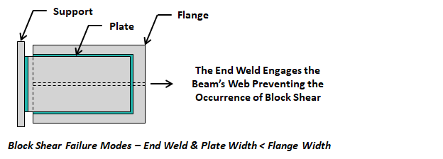
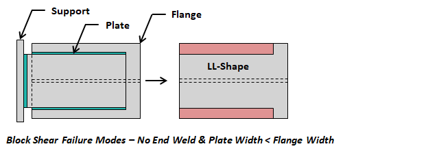
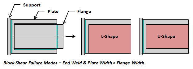
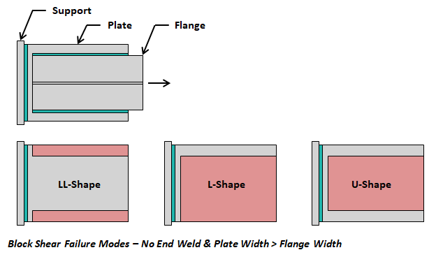
The block shear failure method at the plate-to-flange connection depends on the both the end weld condition and the relative width of the plate to the flange. VAConnect automatically checks the all of the applicable block shear cases as outlined in the figures below.


