A Wood Bolted Shear connection consists of a Main Member and a Side Member connected to one another using one or more steel bolts. The Main Member is a single, solid wood member, while the Side Member can be defined as a single or double member, causing the bolts to be loaded in single or double shear, respectively. The Side Member(s) can be defined using either wood or steel material. VAConnect allows the Side Member(s) to be oriented at any angle relative to the Main Member when a single fastener is used. When multiple fasteners are used, the Side Member(s) must be parallel or perpendicular to the Main Member.
Wood Bolted Shear connections are checked per the American Wood Council, National Design Specification for Wood Construction, 2018 edition (NDS).
Four primary connection yield modes are specified for dowel-type fasteners, which are used to determine the reference lateral design value, Z, for a single fastener.
Mode Im & Is - Bearing-dominated yield of wood fibers in contact with the fastener in either the Main or Side Member(s), respectively.
Mode II - Pivoting of the fastener at the shear plane with localized crushing of the wood fibers near the faces of the wood member(s).
Mode IIIm & IIIs - Fastener yield in bending at one plastic hinge point per shear plane, and bearing dominated yield of the wood fibers in contact with the fastener in either the Main or Side Member(s), respectively.
Mode IV - Fastener yield in bending at two plastic hinge points per shear plane, and localized crushing of wood fibers near the shear plane(s).

The Adjusted Lateral Design Value (Z') is determined by calculating the appropriate Adjustment Factors (C-factors), as shown below.
Z' = Z × CD CM Ct Cg C∆ Ceg Cdi Ctn
where:
CD, Load Duration Factor - NDS Section 11.3.2
CM, Wet Service Factor - NDS Section 11.3.3
Ct, Temperature Factor - NDS Section 11.3.4
Cg, Group Action Factor - NDS Section 11.3.6
C∆, Geometry Factor - NDS Section 12.5.1
Ceg, End Grain Factor - NDS Section 12.5.2
Cdi, Diaphragm Factor - NDS Section 12.5.3
Ctn, Toe-Nail Factor - NDS Section 12.5.4
The Adjustment Factor Reports show details of how each factor is calculated, with the exception of the End Grain, Diaphragm, and Toe-Nail Factors, which are not calculated directly by VAConnect, but can be overridden. Individual Adjustment Factors can be ignored (C = 1.0) or overridden using the Project Settings.
In VAConnect, Axial and/or Shear loads are applied to the Side Member. A resultant load is calculated from the axial and shear components and applied to the bolt group. VAConnect uses the resultant load and the orientation of the member under consideration to determine if the load is parallel or perpendicular to the member grain. The resulting load direction, parallel or perpendicular to the member grain, is used when calculating the Geometry Factor (C∆) and the Group Action Factor (Cg).
As shown in the Figure below, loading is assumed to be Parallel to the Grain when the direction of the resultant load is within 45-degrees of the member's centerline orientation. Conversely, when the loading is outside of this range, the loading is assumed to be Perpendicular to the Grain.

For Parallel to Grain loading, definitions for the End Distance (tension and compression), Edge Distance, and Spacing (between bolts and between rows) values are shown in the Figure below. Note: For the bolt group shown, there are two Rows of Bolts, with each row having three Bolts Per Row.

For Perpendicular to Grain loading, definitions for the Loaded/Unloaded Edge Distance, End Distance, and Spacing (between bolts and between rows) values are shown in the Figure below. Note: For the bolt group shown, there are three Rows of Bolts, with each row having two Bolts Per Row.

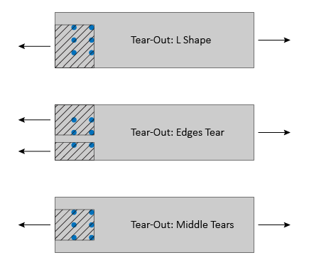
When a wood member is loaded parallel to the grain, the capacity of a group of bolts may be limited by wood failure at the net section or tear-out around the bolt group caused by local stresses. VAConnect checks the Net Section Tension Capacity, Row Tear-Out Capacity, and Group Tear-Out Capacity for both the Main and Side Member(s) according to NDS Appendix E. The Group Tear-Out limit state considers three tear-out groups, as shown in the Figure below.

The local stress limit states are based only on the tension component of the resultant load for the member being considered. In other words, the design load is determined as the component of the resultant load that aligns with the member's centerline. The influence of shear on the Net Section Tension Capacity, Row Tear-Out Capacity, and Group Tear-Out Capacity is not considered by VAConnect.
VAConnect checks the following limit states for Wood Bolted Shear connections (refer to the program’s detailed reports for specific code references):
VAConnect makes the following design assumptions for Wood Bolted Shear connections:
