
IES ConcreteBending User's Guide
Load Points
Load Points in ConcreteBending are used to apply concentrated loads and moments to slabs at a specified location.
Load points are defined by their location, shape, and size in the model. Four shapes are available: Square, Rectangular, Circular and Octagon. The radius of an octagon pier is based on the octagon being inscribed inside a circle with the specified radius. Note: In the Finite Element Analysis (FEA) model, a single node in the slab's mesh is loaded; therefore, care should be taken when specifying load points with large cross-sections.
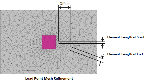
The FEA method is approximate and the accuracy of the FEA solution typically increases as the mesh becomes finer. Generally, a finer mesh should be used in regions where there are large changes in stresses in the plates (such as at load points where concentrated loads can create stress concentrations). Select a load point(s) and set Refine? = True in the tab to refine the mesh in the regions of the chosen load point(s). The mesh refinement parameters for load points are defined in the image below.
Concentrated forces (compression and tension), in addition to moments in two directions can be applied to load points.
During the finite element analysis each load point is modeled as a single node connected to the slab's finite element mesh. Therefore, care should be taken when specifying load points with large cross-sections.
While load points appear to be columns when the Picture View is enabled in ConcreteBending, they do not have any length in the finite element model (i.e. they are not modeled as a member element). Therefore, load points are not designed in the program. Punching shear design checks, however, are checked for the slab at the location of the Load Points.
In ConcreteBending, Punching Shear design checks are performed at load point locations and the program automatically determines the punching shear perimeter (critical section). An individual load point can also define punching shear reinforcement in the form of headed shear studs or shear stirrups located in the slab. Additional information regarding punching shear design checks and punching shear reinforcement can be found in the Slabs - Design section.
Multiple report tables, which include modeling, loading, and result information for the Load Points, are available in the Text Report view.