
IES ConcreteBending User's Guide
Slabs and Walls
Concrete boundaries (also know as slabs or walls) are the primary elements modeled and designed in ConcreteBending. Boundaries with a wide variety of shapes and sizes can be modeled in the program. The concrete boundary can be supported by Point Supports and Line Support and stiffness can be added by modeling Beams into the boundary. A single concrete material is used for all boundaries in the project and is defined in the .
ConcreteBending is used to model concrete boundaries that bend out-of-plane which generally fall into two categories: slabs and walls. A slab's self weight will cause it to bend out of plane whereas a wall's self weight will not. The project can be set to include the self weight (for slab type systems) or exclude the self weight (for wall type systems) in the Project Settings (located in the tab when nothing is selected in the Model and Load view), In this section the concrete boundaries are often referred to as "Slabs", however, the term "Wall" is interchangeable.
In the Model and Load view, circular, rectangular, polygonal, or custom concrete boundaries can be drawn using the buttons in the ribbon. These slabs are defined by the vertices at boundary points. New concrete slabs can be drawn on grids or existing vertices and snap points can be used to create the boundary. The number of snap points along each edge of the slab is specified in the in the tab. Any arbitrary geometry can be constructed by drawing multiple slabs connected to or overlapping each other. Adjoining slabs are modeled as continuous, with common displacements and flexural rotations at the boundaries. Each individual slab boundary can have a different thickness. At locations of overlapping slabs, the thickness is specified using the Thickness Overlap parameter in the tab. Note: Disconnected slabs are not allowed in ConcreteBending and expansion-joints or other discontinuities in the slab cannot be modeled.
A selected slabs can be turned into a hole by setting Hole? = Yes in the tab. Loads that exist within holes are not included in the analysis. If portions of Area Loads lie partially over holes, only the loading lying over slabs are considered (i.e. the loading that occurs over holes is not distributed to adjacent plate elements).
The reinforcement parameters for each slab are defined by selecting the slab from the Model and Load view and editing the Reinforcement Details section in the tab, as described below.
Slabs may be loaded with Full Area, Circular, Rectangular, Tubular, and Ring area loads or by concentrated Point loads. Loads can also be transferred to the slab by Beams.
Finite element analysis is approximate and numerical. Use mesh refinement and examine results carefully, before trusting design checks.
Slabs in ConcreteBending are meshed into triangular FEA plate elements. See the Analysis page for more information on the FEA mesh density, including the available settings and options. For a better understanding of the FEA model that is built by ConcreteBending, use the feature to create a VisualAnalysis project and examine the FEA model in more detail. More information on integration between ConcreteBending and both VisualAnalsyis and VAConnect can be found in the Integration section of the Help File.
The results from the finite element analysis can be displayed graphically in the Analysis Results view. The tab displays the numerical results that correspond to the colored graphics. With nothing selected, the results displayed in the are a summary for the selected result case, whereas if one or more individual plates are selected, the shows the result range for the selected plates. The various Result Cases that were included in the finite element analysis can be selected using the Result Case drop down from the tab. The Result Type displayed graphically in the Analysis Result view is specified in the .
Plate result moment, shear, and displacement diagrams are available in the Analysis Results view. Left-click and drag a line across the slab to view the result at the line's location or right-click and select Show Plate Result Diagram from the context menu to view the diagrams for the selected result case. The slice direction and location can be adjusted within the Plate Result Diagrams dialog box along with the number of plots displayed and the plot type. Note: The result location and plot settings will persist within one session of ConcreteBending. This allows the Plate Result Diagrams dialog box to be closed to select a different result case or to modify the model without losing the adjustments that were made in the dialog.
ConcreteBending checks and designs concrete slabs and walls according to the following design specifications:
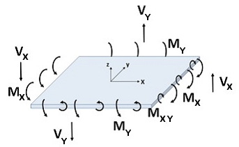
Slabs that experience two-way action have both bending moments (MX and MY) and twisting moments (MXY). The twisting moments may cause the maximum bending demand to not coincide with the X or Y reinforcing directions. To ensure that the slab has adequate strength in all directions, ConcreteBending uses the method by Wood and Armer as explained by MacGregor and Wight1,2 to design the reinforcement. The following equations are used to calculate the design moments which are obtained from Wood and Armer when k=1.0. According to MacGregor and Wight,2 k=1.0 is the best choice for a wide range of moment values. ConcreteBending takes the critical flexure section as the face of Beams, Point Supports, and Line Supports. Plate nodes that fall within these objects are not checked for flexure.
MX+ = MX + |MXY| ≥ 0
MX- = MX - |MXY| ≤ 0
MY+ = MY + |MXY| ≥ 0
MY- = MY - |MXY| ≤ 0
The bending moment capacity of the slab is a function of the compressive strength (f'c), thickness, and the area of steel reinforcement provided. Reinforcing is placed in both plan directions (X & Y) and in either one or two layers. This results in up to four reinforcing quantities at every point in the slab (X, Y, Top, Bottom). ConcreteBending performs moment and steel demand calculations at the finite element model node points. When the slab's reinforcement is set to Optimize (as discussed above), the reinforcement required to meet factored demand is selected by the program based on the list of available rebar patterns. The rebar pattern with the smallest area (As) is selected from this list that meets the required flexural and minimum steel demands. If the slab's reinforcement is set to Specify, the reinforcement pattern defined for the direction and layer in question will be used when performing the design checks.
The critical section for one-way shear (i.e. beam shear) is taken at the face of: Load Points, Point Supports, Line Supports, and Beams. If, however, a Point Support or Load Point introduces compression in the slab, the critical section is taken at "d" from the face of the object.
Plate shear checks are reported graphically in the Design Results view by selecting Shear Unity from the under the Slab Details category (red plate colors indicate a failing unity value). Shear checks can also be reported as numerical results using the programs's Text Reports.
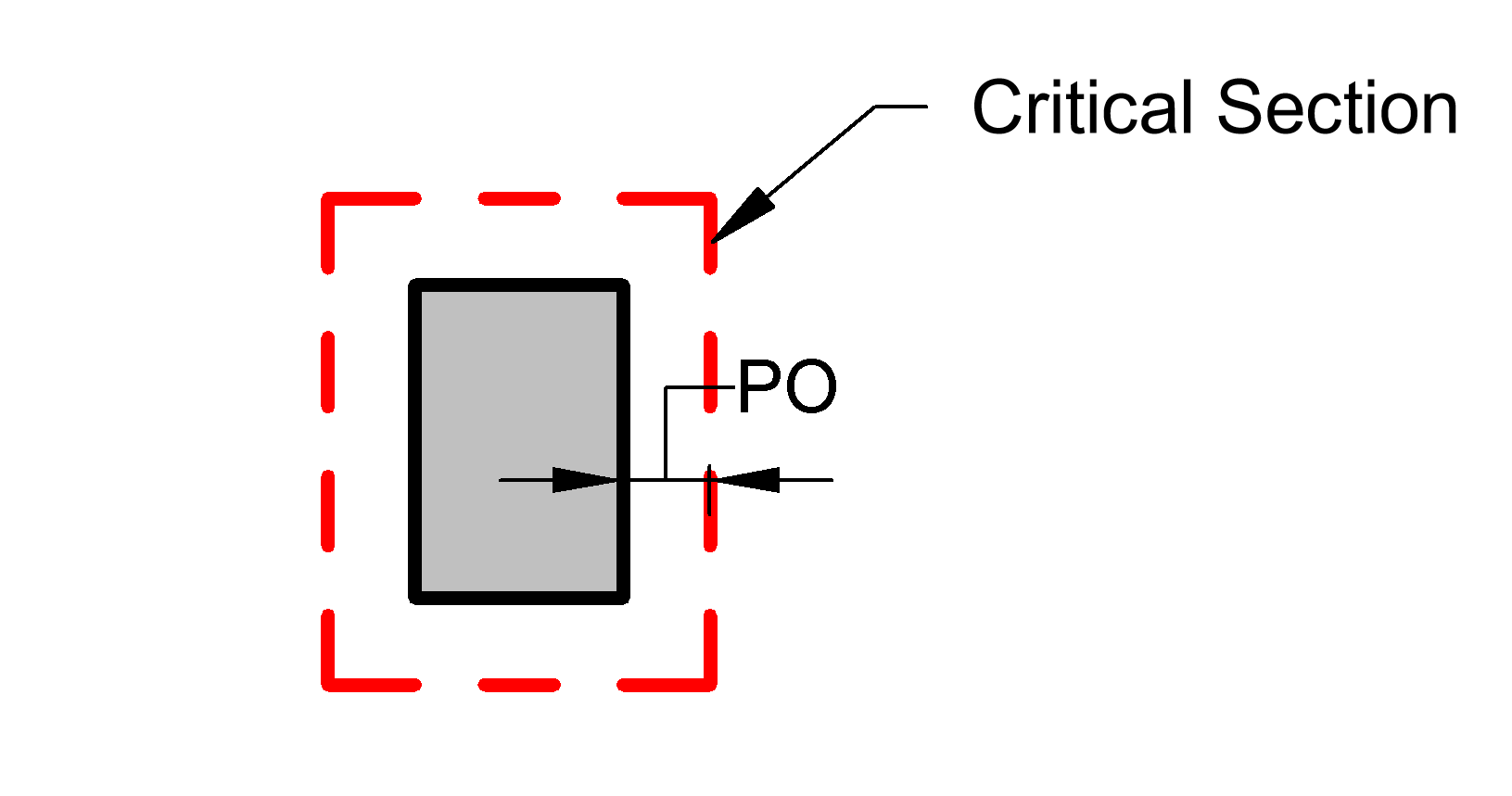
Two-way (i.e. punching shear) checks are made at locations where a concentrated load is introduced into the slab, such as at Load Points, Point Supports, and Line Supports. The design check for punching shear involves calculating the punching perimeter (i.e. Critical Section) around the object, which may be truncated by the slab boundary. The nominal strength of the punching perimeter must exceed the net load acting inside the perimeter.
If a Beam crosses an object's punching perimeter, punching shear checks are not performed ("-N.A.-" will appear in the punching shear report). In this situation, it is assumed that the Beam will be designed to carry the required shear demands. Punching shear checks are not performed for rectangular/circular loads or for beams.
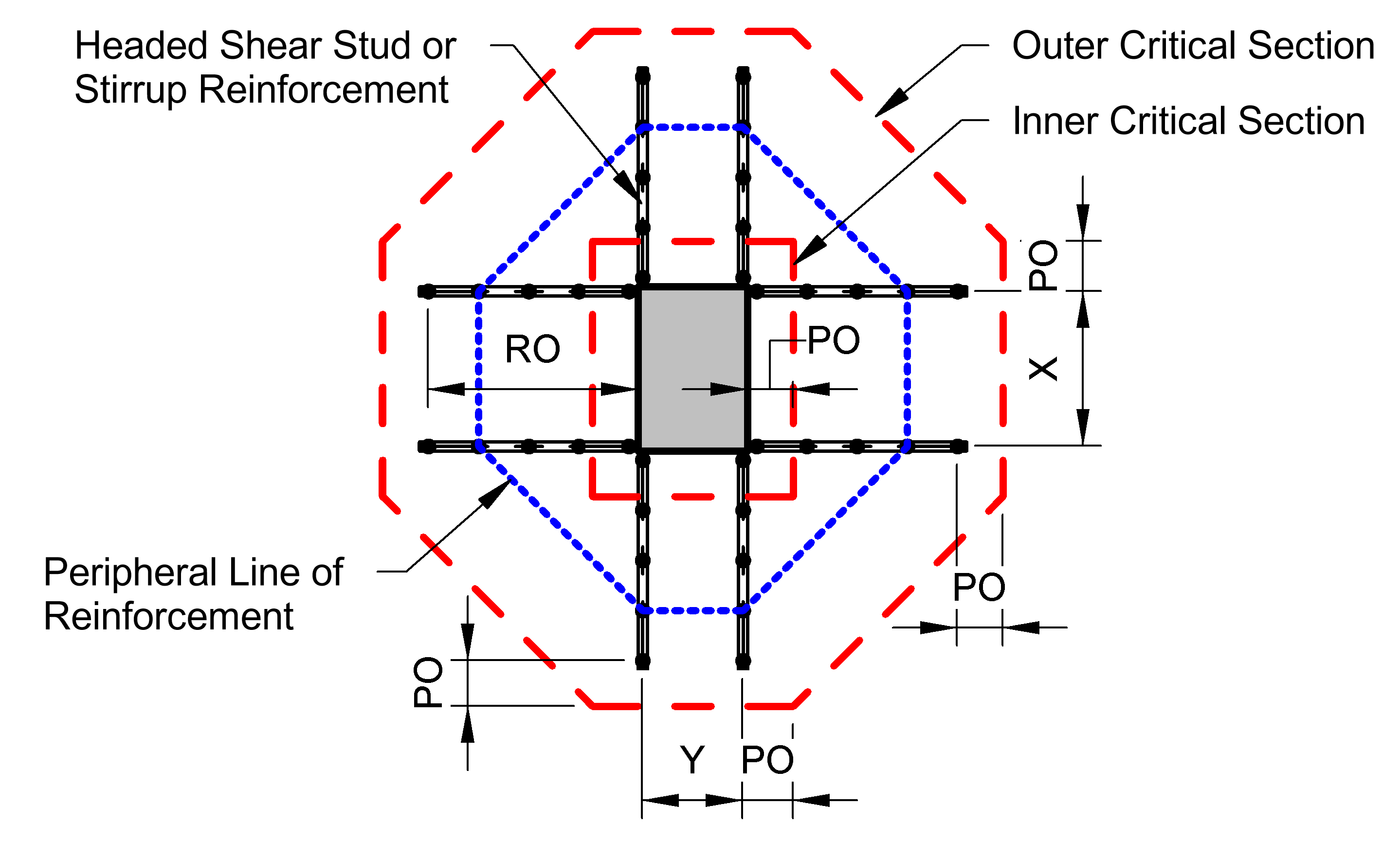
The punching perimeter can be shown graphically on both the Model and Load view and the Design Results view. When punching reinforcement is present (see below), the Outer Critical Section is displayed graphically for the object with reinforcement.
When Load Points or Point Supports contact other surrounding punching perimeters, these are combined into a larger punching area. The same capacity checks are made on the larger combined perimeters. While these combined areas are shown graphically in the Model and Load view, they cannot be directly overridden or manipulated. Note: When the Override Perimeter Offset parameter (see below) is used for an individual object that is part of the punching shear group, it has an effect on the overall punching perimeter for the group as a whole.
Two-way shear reinforcement can be defined for individual Load Points or Point Supports in the form of headed shear studs or shear stirrups. When punching reinforcement is provided, a design check is performed on both the Inner and Outer Critical Section. The slab's capacity at the Inner Critical Section is determined as the sum of the concrete and steel reinforcement capacity. The slab's capacity at the Outer Critical Section is determined from the concrete capacity alone.
Note: The punching shear reinforcement is assumed to extend away from the object in the Global +X, +Y, -X & -Y directions, regardless of the object's shape or orientation. If a slab edge (either an outside edge or hole edge) is located within the Reinforcement Offset distance (see below), the reinforcement is assumed to extend to the edge of the slab in that direction.
Below are the design parameters available for an individual Load Point or Point Support. These parameters can be found from the tab when a Load Point or Point Support is selected from the Design Results view.
| Load Points & Point Supports Without Reinforcement | |
| Override Punching Offset (PO)? | Do you want to override the punching perimeter offset? - Choosing 'No' results in using the slab reinforcement depth (d/2) for the offset. Choosing 'Yes' allows you to enter your own value to be used as the punching perimeter offset. |
 |
|
| Load Points & Point Supports With Reinforcement | |
| Override Punching Offset (PO)? | Do you want to override the punching perimeter offset? - Choosing 'No' results in using the slab reinforcement depth (d/2) for the offset. Choosing 'Yes' allows you to enter your own value to be used as the punching perimeter offset. |
| Are Headed Studs? | Is the reinforcement headed shear studs? |
| Fyt | The yield stress of the reinforcement. |
| Av total | The total area of shear reinforcement around a peripheral line of reinforcement. |
| Spacing | The spacing of peripheral lines of shear reinforcement. |
| X Reinf. Group Width (X) | The width of the stud/stirrup reinforcement group oriented in the Global X-Direction. Enter 0.0 for a single stud rail or stirrup leg line. |
| Y Reinf. Group Width (Y) | The width of the stud/stirrup reinforcement group oriented in the Global Y-Direction. Enter 0.0 for a single stud rail or stirrup leg line. |
| Reinforcement Offset (RO) | The distance from the object face that the shear reinforcement extends outward. |
 |
|
The software can detail bar patterns by plate element, by column lines or by slab boundary. Use the tab from the Design Results view to display the different results. Note: The By Column Line display is not available if the Design Approach is set to Specify.
Reports can include both text-based and graphical information. Graphical information from the Analysis Results or Design Results views or from the plate diagrams can be inserted into a report using the and commands.
Plate result diagrams for moment, shear, and displacement are available in the Analysis Results view and plate design diagrams for shear unity and area of steel required are available in the Design Results view. Left-click and drag a line across the slab to view the diagrams at the line's location or right-click and select Show Plate Result/Design Diagram from the context menu to launch the respective diagram dialog box. The slice direction and location can be adjusted within the dialog along with the number of plots displayed and the plot type. Note: The slice direction and location along with the plot settings will persist within one session of ConcreteBending. This allows the dialog to be closed to select a different result case or to modify the model without losing the adjustments that were made in the dialog. To include graphs in the report, use the copy plots button to copy the plots to the clip board which can then be pasted into the report.
Analysis and design results can also be viewed in text form using the Report View tab. Once in the Report View, a list of available deign tables is shown on the tab and can be added to the text report by double-clicking an individual table or dragging and dropping a table into the report. Plates can also be reported on an individual basis by selecting one or more plates from the Analysis Results or Design Results view, and using the right-click context menu to Report Selected. Note: The reinforcement settings are included in the Slabs table located under the Structure Tables category.