
IES ConcreteBending User's Guide
Point Supports
Point Supports in ConcreteBending are used to support the concrete slab at a specified location in the model.
Point Supports are defined by their location, shape, and size in the model. Four shape types are available: Square, Rectangle, Circle, and I Shape. The size and shape of the Point Support can be specified which influences the calculation of the bending and one-way shear checks for a slab supported by the Point Support. Bending in the slab is always calculated at the face of the Point Support. Shear is calculated at the face of the Point Support if the slab is in tension and at a distance “d” away from the face of the Point Support if the slab is in compression. Note: In the Finite Element Analysis (FEA) model, only a single node in the slab's mesh is restrained at a point support; therefore, care should be taken when specifying point supports with large cross-sections.
ConcreteBending only allows deflection in the Z-direction and rotation about the X-axis and Y-axis. Therefore, Point Supports have the option of being set to Fixed, Free, or Specified-K (stiffness) for Force-Z, Moment-X, and Moment-Y.
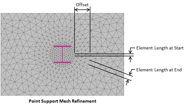
The finite element analysis (FEA) method is approximate and the accuracy of the FEA solution typically increases as the mesh becomes finer. Generally, a finer mesh should be used in regions where there are large changes in stresses in the plates (such as at point supports where the support can create stress concentrations). Select a point support(s) and set Refine? = True in the tab to refine the mesh in the regions of the chosen point support(s). The mesh refinement parameters for point supports are defined in the image below.
Point Supports cannot be directly loaded in ConcreteBending. A load point can be defined at the same location as the point support (i.e. connected to the same node in the finite element model) and load can be applied to the load point.
The force in the Z-direction and the moments in the X-direction and the Y-direction are calculated for each load case and reported for the Point Supports in ConcreteBending. The displacement in the Z-direction and the rotations about the X-axis and the Y-axis are also reported. The slab punching shear results from a Point Support are reported when applicable.
While point supports appear to be columns when the Picture View is enabled in ConcreteBending, they do not have any length in the finite element model (i.e. they are not modeled as a member element). Therefore, point supports are not designed as axial members in the program. Punching shear design checks, however, are performed for the slab at the location of the point supports.
In ConcreteBending, Punching Shear design checks are performed at point support locations and the program can automatically determine the punching shear perimeter (critical section). An individual point support can also define punching shear reinforcement in the form of headed shear studs or shear stirrups located in the slab. Additional information regarding punching shear design checks and punching shear reinforcement can be found in the Slabs - Design section.
Multiple report tables, which include modeling and result information for the Point Supports, are available in the Text Report view.