IES VisualAnalysis User's Guide
Aluminum Design
VisualAnalysis designs aluminum members according to the following Aluminum Design Manual (ADM) specification produced by the Aluminum Association:
Aluminum members are designed for tension, compression, flexure (strong axis and weak axis), shear, and torsion to resist the varying demands along the length of the member. When necessary, the interaction of these loads are accounted for in the design checks per the selected design specification. The maximum unity value (demand to capacity ratio) for the member is shown in both the Design View and in the Report View, allowing the user to quickly identify if the member is passing (unity ≤ Unity Success Limit) or failing (unity > Unity Success Limit). In addition to checking the capacity for aluminum members, VisualAnalysis can check the deflection limits for the members based on the deflection limits set by the user and the Deflection Check load combinations. The shapes for aluminum members can be manually adjusted in the tab until a satisfactory design is reached or VisualAnalysis can automatically optimize the shape for the Design Group using the Design the Group button in the Design Ribbon. Appropriate load combinations (Strength for LRFD, Allowable for ASD) must be used to obtain design checks.
VisualAnalysis can perform aluminum design using Database Shapes, Standard Parametric shapes, or custom shapes that have the required shape properties for design. For example, the ADM standard shapes in the IES Shape Database can all be designed according to the aforementioned ADM design specifications. The IES Shape Database can be customized to include libraries of custom, foreign, or legacy shapes. The following Standard Parametric shapes are supported by VisualAnalysis for aluminum design: angle, channel, circle, I-shape, pipe, rectangle, rectangular tube, tee and zee (spandrel shapes are not supported for aluminum design). Custom shapes can be created using IES ShapeBuilder and are supported for aluminum design in VisualAnalysis given the required shape properties.
The St. Venant torsional shear stress is calculated from the torsional moment and added to the shear stress calculated in VisualAnalysis. Torsional Warping stresses are not considered. Therefore, cross-sections that are not "closed shapes" are not fully checked if torsion is present. The maximum torsional moment can be reported to help the user check for other torsional stresses that may be present.
By default, the unbraced length for a member is assumed to be the member-element length between nodes. The lateral top/bottom unbraced length is used for the flexural design checks while the strong unbraced length is used for the compression design checks. See Bracing for more information on member bracing.
A variety of options are available to specify the deflection limits. To obtain deflection checks, deflection load combinations must be included in the in the Load Case Manager. More information is available on the Deflections Page.
Several parameters must be defined to design aluminum members in VisualAnalysis. The design parameters are set in the tab when the Design View is selected. After creating a Design Group, choose one of the members that belongs to the group in the Design View to set up the Design Group's Parameters. Since the design parameters apply to all members in the Design Group, it is often best to choose the most conservative condition that applies to any member in the group.
| Aluminum |
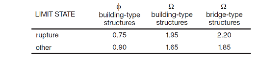
Specification - The Design Specification used to design the members in the Design Group. Bridge-Type Structure - Choose to use bridge type φ and/or Ω factors. Heat Affected? - Specify if the members should be designed with the heat-affected 'w' values (heat-affected members are usually welded). Select Partial Length to specify the portion of member length at each end to use the welded material properties. Design checks are performed with Ftyw, Ftuw, Fcyw, Fsuw stress values in the heat affected zones. Overstrength? - Causes the Design Group to be designed using overstrength load combinations. Live Load Reduction - If specified, design checks will only consider result cases with the matching live load reduction. Combinations with live load reduction can be created in the . Disable Checks? - Causes selected Design Group to be omitted from design checks. This feature can be used to speed up design checks and focus on targeted areas of larger models. Check Level - Determines the level of detail reported from design checks. Options are: To Failure (Fastest), Each Limit State, and All (Slowest, but provides the most information). |
| Bracing |
Lateral Top (+y) - Lateral bracing at the top side of the member (+y). Choose a bracing arrangement. Lateral Bottom (-y) - Lateral bracing at the bottom side of the member (-y). Choose a bracing arrangement. Strong (z) - Brace against strong-axis buckling for columns. |
| Deflections |
Strong (dy) - Specify the type of limit for beam deflections in the y-direction. Use Total to include the displacements of the nodes at each end of the element. Weak (dz) - Specify the type of limit for beam deflections in the z-direction. Use Total to include the displacements of the nodes at each end of the element. |
| Size Constraints |
Limit Depth/Width? - Allows the design search to 'Fail' if the shape is outside the Min/Max range. |
| Axial |
Manual Kz/Ky - Allows the user to manually override the effective length factors for the strong/weak axis. Kz/Ky Sidesway? - Choose if the member is apart of a sway frame in the specified direction. |
| Overrides |
Override Cb? - Disable the automatic determination of Cb and allows a custom value to be used. Override Fty, Ftu, Fcy, Fsu? - Override the stress parameters used for the design and unity checks. The value of Fsy will be affected by Fty. These overrides only affect the portions of the members that are not Heat Affected. Override Ftyw, Ftuw, Fcyw, Fsuw? - Override the stress parameters used for the heat affected sections for design and unity checks. These overrides only affect the portions of the members that are Heat Affected. |
To achieve an adequate design, the section for the members in a Design Group can be manually adjusted until all the design checks pass. Alternatively, the built in optimization feature in VisualAnalysis can be used to find an adequate shape for the members in a Design Group. The optimization feature can be used to search for adequate Database Shapes or to iterate through the parameters of a Standard Parametric shape until an adequate shape is found.
1. Create the Members
In the Model View draw or create the Aluminum members.
2. Support and Load the Members
Define support conditions for the model and apply the service level loads to the members. Set the load combinations in the Load Case Manager.
3. Specify the Parameters
Select a preliminary Aluminum Database Shape or Standard Parametric Shape and set the material properties.
4. Analysis and Preliminary Design
VisualAnalysis will automatically analyze the model and perform the appropriate design checks. Simply click on the Results View tab to view the analysis results for the model or the Design View tab to see the design results.
5. Create/Modify Design Groups
VisualAnalysis will automatically create groups for members based on material, orientation, length, and/or cross-section. Alternatively, Design Groups can be created or modified manually as explained in the Groups Category.
6. Define the Parameters
For each Design Group, set the Aluminum parameters (design specification, structure type , heat affected regions, etc.) in the in the tab in the Design View. Also, adjust the bracing, deflections, size constraints, axial, and overrides for the design group as needed.
8. Design the Group
After selecting a Aluminum design group, click the Design the Group button in the Design ribbon. In the Design Selection dialog box, choose the search type (Database or Parametric) and set the number of shapes to be returned from the optimization. For a database search, choose which database is to be searched and the category of shapes that are to be searched within the database. Also, set the size constraints if needed. For a Parametric search, select the parametric type (I-Shape, Angle, Channel, etc.) and specify the search range (Start and End) and the Increment for each parameter of the shape or choose to hold the parameter constant. Once the search parameters are set, click the Optimize Now button to search for various sections and display the unit value for each shape. If a warning stating "demands could not be satisfied" appears, then all the shapes within the search parameters have a unity value larger than the Unity Success Limit defined in the Preferences. Enabling the Return all Shapes feature will provide information on every considered section which may be useful for determining why a section failed or was not optimal.
9. Select a Section
Once the optimization is complete, select a section from the list and click the Accept Design button. Now the unity value for all members in the design group are displayed using the selected section. The tilde symbol (~) in front of the unity value indicates that the unity checks must be validated with another analysis since the member stiffness and resulting load distribution may have changed.
10. Synchronize Design Changes
Click the Synchronize Design button in the Design ribbon to automatically update the model with the new cross-section, re-analysis the model with the new member stiffness, and rerun the design checks with the updated analysis results.
11. Verify Unity Ratios
The final step in the design process is to verify that Unity Ratios in the Design View are less than the Unity Success Limit defined in the Preferences. If member sizes were drastically changed during the design process, final unity ratios can differ from predicted unity ratios because the analysis results may vary significantly.
The aluminum design reports in VisualAnalysis are highly customizable. To control what is included in a report, simply click on a table in the report and adjust the settings in the tab. The Extreme Rows feature is particularly useful to produce concise reports of only the controlling cases or to produce detailed reports that display every design check that is made. When this feature is set to Show All, the reports may become excessively large which can be controlled by adjusting the Conciseness feature. The reports for aluminum design include both a summary of the parameters input for the Design Group and tables that included the various design checks. These tables have the following columns:
| Column Name | Description |
|---|---|
| Member | The member's name. |
| Section | The member's cross-section (e.g. C5x3.55). |
| Offset |
This is the distance from the 'start' end of the member. The number and locations of offsets are as defined in the performance settings in VisualAnalysis. |
|
Result Case |
The result case that is used for the design check. |
| Demand/Capacity | These columns varies depending on the type of design check. In most cases these values are used directly in the unity check, but there are some special cases where the unity checks also include intermediate values or other values that not reported. |
| Code Reference |
The controlling equations or provisions from the chosen design specification. For example, "G.2-1" refers to the equation in the specification while "F.4" refers to a section in the code. |
| Unity Check | The unity check value for this particular member, load case, and offset. Unity checks are calculated as the absolute value of an actual force divided by an allowable strength [ASD] or as the ultimate force (factored) divided by the design strength (factored) [LRFD]. |
| Details | Intermediate values and other information which can be helpful for validating results. |