
IES VisualAnalysis User's Guide
Areas
Areas are used to generate plate element meshes (to represent structural floors, walls, or roof systems) and/or to distribute loads to member or plate elements in the model. Applying loads to areas instead of applying them to members or plates can save time during the design process. For example, if a beam moves in the model, the load from the Area is adjusted automatically and eliminates the need to recalculate and modify the load on the beam. Areas alone have no mass, no stiffness, and offer no support in the model (Areas are not part of the finite element model that gets analyzed), but simply represent the floor, wall, or roof system in the model used primarily for loading the actual elements in the model. Therefore, member or plate elements should always be created corresponding to the Areas in the structural model.
Areas can be manually created by sketching them in the Model View using the command. Drag to define the first edge, click subsequent grid points or existing nodes to define subsequent edges. and Double-click the final point or click on the first point created to close the Area. Unlike Plate Elements which are defined by three or four nodes, Areas are defined by three or more vertices. Vertices can coincide with nodes in the model, but are not depended on nodes and do not move if the node is moved (there is no way to tie vertex locations to the node locations).
Areas can be generated automatically using the command to generate exterior areas or all possible areas (both internal and external). Generated areas may not be perfect so they may need to be adjusted or unwanted areas may need to be removed. Areas can also generated based on the extents of the selected model items (nodes, elements, etc.) using the command.
At times, it is convenient to automatically generate plates then convert the plates to manual plate elements using the command. Converting an area mesh to regular plate elements disables auto-meshing for the area.
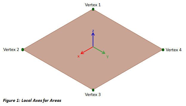
Areas have a local coordinate systems with the origin located at the centroid area. The local x-axis is parallel to and in the direction of a vector from the first vertex to the second. The local y-axis is perpendicular to the x-axis and in the plane of the area. The right-hand rule is used to defined the local z-axis which is perpendicular to the plane of the area. The local coordinate system for a rectangular area is shown in the figure below. The local axes of the area are used when applying plate loads. When drawing multiple areas, it is helpful to be consistent and select the vertices in either a clockwise or counter clockwise direction so that the z-direction is the same for all areas. An arrow illustrating the area's normal direction can be turned on and off in the tab. The command can be used to flip the top and bottom of the selected areas.
Since Areas are defined by vertices, not nodes, they do not automatically "track" movements or changes in the model. Use the tab to display Area Vertices in the model. Select Vertices in the Model View or in the Find Tool to adjust their location or to move them in the tab. Editing Vertices can cause the size, shape, and/or location of the Area to change. Select an area and use the or commands to adjust the location or orientation of the Area in the model, respectively.
Holes are areas embedded within other areas that do not receive loads. Corridors are embedded areas that can receive higher loads, such as for IBC / ASCE 7 load requirements. Embedded areas are defined by sketching an area within an existing area. After drawing an embedded area, specify its type in the tab.
For Areas, the Span Type can be set to One Way or Two Way to specify how the loads are transferred to the in-plane supporting members. One Way spans are typical for joist systems where closely spaced parallel members carry loads to girders. Two Way spans are typical when the distance between beams and girders is similar causing the load toe be transferred both ways. When plates are loaded with areas, this setting has no effect.
Since Areas alone have no stiffness, to model the stiffness of a floor, wall, or roof Plate Elements can be generated from Areas using the Generate Plates Feature in the tab. Existing nodes and members within the plane of the area are incorporated into the generated plate mesh. Areas that contain manual plates cannot be meshed.
The sides of meshed Areas can be supported similar to nodes. Side supports are defined by selecting one of the Area sides in the Model View and selecting from the available constraints under Support in the tab. Side supports simply support all meshed nodes along the boundary and are automatically updated if the area is remeshed. If the Auto Generate Sides? feature is disabled, side Area Sides can be created using the command.
Select an Area and use the command to apply a uniform load normal to the area. After an Area Load has been created, it can be selected and the following parameters can be modified:
In addition to being loaded in the normal direction, load can be applied to the sides of an Area using the Load command. Area Side Loads consist of forces, moments, settlements, and rotations can be applied in the global X, Y, or Z directions.
Area Results are only available for areas that have Generated Plates. Area Side Results are obtained from the plate forces applied to nodes along the edge and are useful for designing shear walls and diaphragms since total or average results are more convenient to work with than individual plate element results. Results are available as the Average, Detailed, or Total forces calculated for each Area side and the In-Plane Shear, In-Plane Axial, Flexural Shear, Flexural Moment, and Overturning Moment are reported. The sign convention depends on the direction that Areas were drawn. The direction for the sides can be shown by enabling the Side Direction option in the tab.