
IES VisualAnalysis User's Guide
Plate Elements
Plate or shell elements are useful to model walls, slabs, roof systems or other flexible diaphragms either in bending or in shear. Mathematically plate elements are thin, 2D areas that may be represented as quadrilateral or triangular shapes (they do not exhibit through-thickness stress variations like a 3D brick element). Since the finite element analysis method always produces approximate results it is crucial to refine the mesh until the results converge to minimize the error between the calculated solution and the actual solution. There is always a trade-off of performance vs. accuracy when using plate meshes. Generally an increased number of plates produces more accurate results, but requires more time to analyze and can increase the length of reports.
In VisualAnalysis, plates can be drawn manually or generated automatically using Areas. Use the command to draw either triangular (3-nodes) or quadrilateral (4-nodes) plates on the Grid or to existing nodes in the Model View. To create a triangular plate element using this feature, double-click on the last point (when four points are selected, a quadrilateral plate is created automatically). Plates can also be created using the feature based on three or four existing nodes in the model. To create plates using Areas, draw an Area using the command and enable the Generate Plates feature in the Meshing section of the tab for the selected Area. The Mesh Element Area in the Project Settings will control the size of elements in the mesh unless the Override Mesh Size feature is used to set the Element Area for a selected Area. Auto-generated plates require the advanced level of VisualAnalysis, but offer more flexibility, separation of loads from plates, and provide edge results that are easier to interpret. After plate elements are created, they can be selected to specify the thickness and material properties. Note: The Weightless parameter can be used to include or exclude the weight of particular element(s) in the analysis.
At times, it is convenient to automatically generate plates then convert the plates to manual plate elements using the command. Converting an area mesh to regular plate elements disables auto-meshing for the area.
A plate element will account for bending with transverse shear effects in thick plates and rotational drilling degrees of freedom. It is important to note that these formulations are not coupled during the initial analysis. The stiffness matrix for each formulation is computed separately in local coordinate space. The two formulations are assembled into a total 6 degree of freedom (DOF) global element matrix. Once assembled into the global element matrix, the element is combined into the total structural stiffness matrix. Membrane and bending coupling is achieved with the addition of geometric stiffness terms in the overall stiffness matrix. The additional stiffness terms result from membrane strains which are calculated during the initial analysis. Once the membrane strains are found the element stiffness is automatically updated to account for the extra stiffness terms resulting from membrane strains. The plates's bending behavior can be disabled using the tab when a plate or area is selected. Both the membrane and bending formulations are based on triangular elements. When quadrilateral element is used, internally four triangles are used with a middle node which is removed through static condensation thus creating the quadrilateral.
The bending behavior of the plate element is based on the triangle formulation originally presented by Xu et. al. in 1992, which includes transverse shear effects.1 Prior versions of VisualAnalysis and many finite element analysis packages use the discrete Kirchoff triangle (DKT) as their primary thin plate element. Although the DKT element is a reliable and widely used element for plate analysis, it cannot accurately model thick plates. The new element accounts for transverse shear effects present in structures that might contain areas with thick plates, such as footings or thick floor slabs.
Drilling degrees of freedom are included in the plate element, resulting in a 3-DOF per node plate element. Therefore, a moment can be applied perpendicular to the surface of the plate element at any of the three (triangle element) or four nodes (quad element). Elementary membrane elements ignore drilling dofs in order to avoid membrane locking. Membrane locking in the new element was avoided by independently interpolating the drilling rotations over the element and introducing a penalty stiffness based on the shear modulus. The membrane element presented in VisualAnalysis is based on the early work of Allman.2 The element is similar to the standard CST membrane element but includes an additional rotational degree of freedom at each node. VisualAnalysis uses 4-point symmetric integration using the points from Cook, which gives good results and matches the data from Allman's paper.3 Drilling DOF in membrane elements are difficult as all elements exhibit "membrane locking" and zero-energy modes, these issues can become prominent in coarse meshes.
Both thin and thick plates can be modeled using VisualAnalysis as thick plates automatically include the effects of transverse shear deformations important for modeling foundations and footings. The quadrilateral element formulation can handle elements that are not square. While elements can be distorted without problems, the best results are obtained when the element aspect ratios are close to 1:1. Elements with larger aspect ratios (of 5:1 and higher) have been tested and have produced reasonable results.
By default, plate elements are rigidly connected to adjoining plate elements at the nodes in all directions. Select one or more plates to modify the releases at each node in the local coordinate system. Situations where numerous plate elements all connected to a single node should be avoided for efficiency reasons. This situation commonly happens at the center of a circular disk, with radially generated plate elements (consider adjusting the mesh near the center to alleviate the problem).
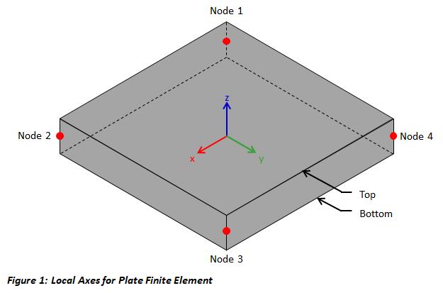
Plate elements have a local coordinate systems with the origin located at the centroid of the plate. The local x-axis is parallel to and in the direction of a vector from the first node to the second. The local y-axis is perpendicular to the x-axis and in the plane of the plate. The right-hand rule is used to defined the local z-axis which is perpendicular to the plane of the plate. The local coordinate system for a rectangular plate element is shown in the figure below. The plate local axes are used when applying plate loads and for reporting local forces and stresses. When manually drawing multiple plate elements, it is helpful to be consistent and select the points in either a clockwise or counter clockwise direction so that the z-direction is the same for all plates. Use the tab to show plate local coordinates. The command can be used to flip the top and bottom of the selected plates.
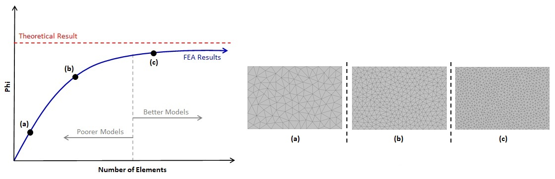
It is the user's responsibility to verify and validate the results obtained from VisualAnalysis. The finite element method is approximate and the accuracy of the solution depends on how fine the mesh is in the model (generally, a finer mesh produces more accurate results). A finite element mesh refers to the multiple plates that are used to model a single component (such as a slab or a wall). Mesh Refinement is the process of reanalyzing the model with successively finer and finer meshes and comparing the results between these different meshes. As the mesh is refined, the change in the solution becomes smaller and an asymptotic behavior of the solution starts to emerge as shown in the figure below. Eventually, the changes to the solution will be small enough that engineering judgment can be used to determine that the model has converged.
Plate elements in VisualAnalysis are meshed manually using the command and the mesh refinement must be performed manually. Mesh refinement for plates generated from Areas (which requires the Advanced Level) is accomplished by reducing the Mesh Element Area in the . In general, a finer mesh should be used in areas where there are large changes in stresses and forces in the plates (such as at stress concentrations or at locations near concentrated loads).
Note: Model results such as displacement, moment, shear, etc., which are represented as Phi in the graph below, will coverage a different rates. Therefore, it is important to ensure that the model has converged for the results of interest.
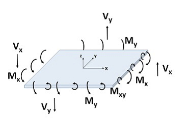
The moment and shear forces for out of plane bending and the in-plane normal or shear stresses can be reported for plate elements. Plate forces and moments are reported per unit length of plate. Moments have units of force*length/length and shears have units of force/length. Plate membrane stresses may also be output relative to the global or local axes.
The sign convention for moments is that a positive moment produces tensile stresses on the +z local coordinate face of the element, as shown in the image below.
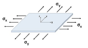
The image below shows the sign convention for tensile normal stresses which are positive.
When plates experience bending, the stresses can be reported for the top and bottom faces. Stresses at the face are combined bending and membrane stresses. If plates are subject to bending stresses only, the neutral axis is at the mid-plane and therefore the normal stresses at this plane are zero.
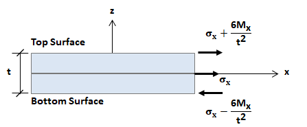
Plate forces and stresses can be reported with respect to the global coordinate system. This simplifies interpretation of the results when the local axes of elements in a complex mesh are aligned. The global forces follow the right-hand-rule for sign convention where a positive MX moment is at the global X edge of the plates and rotates about the global Z-axis. Some results may be zero after the transformation to the global directions, for example the global-Z moment for a mesh lying in the X-Y plane. Plate results can be seen graphically in Result Views, or in various report tables.
The Von Mises stress, σv, can be reported for plate elements in VisualAnalysis and is defined as follows:
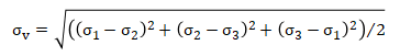
where
σ1 = principal maximum stress.
σ2 = principal minimum stress.
σ3 = zero since a thin-plate element is used with no through-thickness stress.