
IES VisualAnalysis User's Guide
Composite Steel Beam Design
VisualAnalysis performs the design of composite steel beams according to the following design specifications:
Composite steel beams design is based on the Steel Design provisions. When a steel design group is marked as composite beam, sections for the concrete slab, deck, and studs appear in the tab to specify the additional parameters required for the composite beam member.
The construction type for composite beams can be set as Shored, Unshored (Approximate), or Unshored (User Defined). When specified as Unshored, the non-composite flexural capacity of the beam is checked for the construction loading. In addition to checking the flexural capacity for composite steel beams, VisualAnalysis can check the deflection limits for the composite members based on the deflection limits set by the user and the Deflection Check load combinations. Composite steel beam deflections are determined using the lower bound moment of inertia as described in the AISC specification. The maximum unity value (demand to capacity ratio) for the member is shown in both the Design View and in the Report View, allowing the user to quickly identify if the member is passing (unity ≤ Unity Success Limit) or failing (unity > Unity Success Limit).
To effectively use VisualAnalysis to design composite beam members, only the steel member should be modeled. The stiffness from the concrete slab or from member offsets should not be included in the model as these will be automatically accounted for in the design checks. Note: Engineering judgment should be used to determine if modeling the members without the composite action stiffness is valid for the specific situation.
Several additional parameters must be defined to design composite steel beams in VisualAnalysis. The design parameters are set in the tab when the Design View is selected. After creating a Design Group, choose one of the members that belongs to the group in the Design View to set up the Design Group's Parameters. Since the design parameters apply to all members in the Design Group, it is often best to choose the most conservative condition that applies to any member in the group. The following parameters must be defined in for composite beams in addition to the Steel Design Parameters.
| Bracing (Pre-Composite) |
Lateral Top (+y) - Lateral bracing at the top side of the member (+y) for the pre-composite condition. Choose a bracing arrangement. (Only Applies to Unshored Construction types) Lateral Bottom (-y) - Lateral bracing at the bottom side of the member (-y) for the pre-composite condition. Choose a bracing arrangement. (Only Applies to Unshored Construction types) |
| Concrete Slab |
Construction Type - Define the pre-composite demands (strength and deflection) for the beam-slab system.
Strength, f'c - Specifies the 28-day compressive strength of the concrete. Thickness - Specifies the slab height, as measured from the top of the slab to the top of the steel beam. Weight - Selects from typical concrete unit weights. Lightweight concrete may reduce shear stud capacity. Beam Spacing - Defines the distance between adjacent beams. The effective slab width is based on this value. Conservatively use the smallest applicable distance. Is Spandrel? - If members in the group are spandrel beams (at the edge of the slab), check this box and enter the slab overhang. |
| Deck and Anchors |
Anchors - The anchor parameters (type, Fu, length, distance from stud to deck web, and number of rows) and spacing regions (member divisions and spacing for each division) are specified in the Steel Anchor Parameters dialog box. Deck Type - Specify whether or not there is a metal deck and the deck's orientation. This setting affects shear stud capacities, size, and spacing requirements. When the deck type is set to parallel or perpendicular ribs, a deck profile (Vulcraft or ASC) can be selected from the database or the rib height, rib width, rib spacing, and deck weight can be manually entered. |
The Construction Type is used to define the pre-composite demands (strength and deflection) for the beam-slab system. The Construction Type for the Design Group is set in the Concrete Slab section of the tab. The Construction Type can be set to Shored, Unshored (Approximate), or Unshored (Defined Loads). The following table summaries the capabilities and limitations of each Construction Type.
|
Shored |
Unshored (Approximate) | Unshored (Defined Loads) | |
| Pre-Composite Strength Checked |
No |
Yes |
Yes |
| Pre-Composite Deflection Checked |
No |
Yes |
Yes |
| Composite Strength Checked |
Yes |
Yes |
Yes |
| Composite Deflection Checked |
Yes |
Yes |
Yes |
| Requires Construction Load Combinations |
No |
No |
Yes |
| Simple Span Assumption |
No |
Yes |
No |
| Uniform Dead Load Assumption |
No |
Yes |
No |
For the Shored Construction Type, the beam is assumed to be continuously shored during construction resulting in no pre-composite demands. Therefore, no permanent pre-composite deflections exist and the pre-composite capacity of the member is not checked. For this case, the non-construction loads (Dead, Live, etc.) should be applied to the system (e.g. the loads that the beam-slab system will experience after the concrete deck has cured, the shoring is removed, and the beam and slab act as a composite or partial-composite system). Construction Load Combinations are not needed for the Shored Construction Type.
For the Unshored (Approximate) Construction Type, the pre-composite demands (strength and deflections) are automatically calculated and checked in VisualAnalysis using an assumed simple-span beam model loaded uniformly by the self-weight of the beam, the weight of the concrete deck, and the weight of the permanent metal deck form (if any). Note: These assumptions may or may not match the analysis model and it is up to the user to decide if the assumptions are valid for their particular case. The pre-composite capacity checks are automatically made using the 1.4D LRFD or 1.0D ASD load combination depending on the chosen design specification (note: construction live loads are not considered for this construction type). The permanent pre-composite deflection limits are automatically checked when the deflection design parameters are specified. For the Unshored (Approximate) Construction Type, the non-construction loads (Dead, Live, etc.) should be applied to the system (e.g. the loads that the beam-slab system will experience after the concrete deck has cured, the shoring is removed, and the beam and slab act as a composite or partial-composite system). The non-construction dead load should included the self-weight of the beam, the weight of the concrete slab, the weight of any permanent deck forms in addition to any other dead loads on the system. The capacity and deflection limits of the composite or partial-composite system are checked for the specified Strength and Deflection load combinations in the Load Case Manager. Construction Load Combinations are not needed for the Unshored (Approximate) Construction Type. VisualAnalysis automatically accounts for the permanent pre-composite deflection in the composite deflection checks.
For the Unshored (Defined Load) Construction Type, the analysis results from the load combinations marked as 'Construction' are used to determine the pre-construction demands on the beam. Creating construction load service cases allows the Construction Strength and Deflection load combinations to be easily defined. The non-composite strength of the steel beam is checked to ensure that it can support the demands from the Construction Strength Load Combinations. The pre-composite deflections limits are checked using the stiffness of the non-composite steel beam for each Construction Deflection Load Combination and the permanent pre-composite deflections are calculated using the Construction Deflection Load Combinations that only have loads from a Dead Load source. The dead load in the non-construction Strength Load Combinations should include the self-weight of the beam, the weight of the concrete slab, the weight of any permanent deck forms in addition to any other dead loads on the system. The dead load in the non-construction Deflection Load Combinations should not include the included the self-weight of the beam, the weight of the concrete slab, or the weight the permanent deck forms (i.e. only include dead load that was not included in the construction load cases) since the permanent pre-composite deflection is automatically added to the composite deflection.
When the Construction Type is set to Unshored (Approximate or Defined Loads), the lateral bracing at both the top and bottom of the member can be specified for the pre-composite condition. When the Construction Type is set to Shored, VisualAnalysis assumes the beam is fully shored and does not perform any pre-composite checks. Consequently, no pre-composite bracing parameters are required for the shored construction case.
The concrete deck is assumed to continuously brace the top flange of the beam for the composite condition. The bottom flange of the beam is assumed to be unbraced and the unbraced length is assumed to equal the members length.
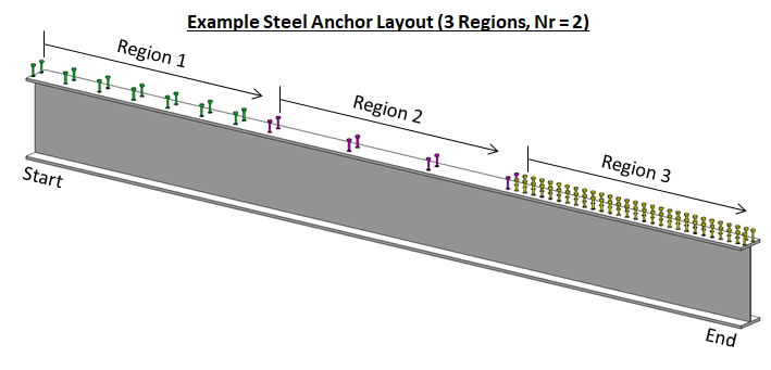
Composite beams can be divided into multiple regions and the steel anchor spacing can be defined for each region as shown in the image below. Steel anchors are placed at the start of a region (i.e. the region's side closest to the start of a beam) and spaced equally until the next region is reached. Since the number of rows, Nr, is specified for the entire member, it cannot vary for the different regions of a member.
The flexural capacity for both the pre-composite beams and the composite beams are calculated and checked against the analysis results (demand) in VisualAnalysis.
The non-composite steel beam flexural strength is determined according to Chapter F of the AISC 360 Specification for Structural Steel Buildings. The lateral-torsional buckling modification factor, Cb, is determined automatically from the analysis results. The unbraced length, Lu, is determined from the user specified parameters defined in the Bracing (Pre-Composite) section of the tab.
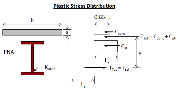
The composite steel beam positive flexural strength (i.e. the concrete is subject to flexural compression) is determined according to Chapter I of the AISC 360 Specification for Structural Steel Buildings and Part 3 of the AISC Steel Construction Manual. The positive flexural strength is determined from the plastic stress distribution on the composite section for the limit state of yielding (plastic moment) as shown in the image below. The composite capacity of the beam depends on the location of the Plastic Neutral Axis (PNA). The shear force between the steel beam and the concrete slab transferred by the steel anchors is the lowest value based on the limit states of concrete crushing, tensile yielding of the steel section, or the shear strength of the steel anchors.
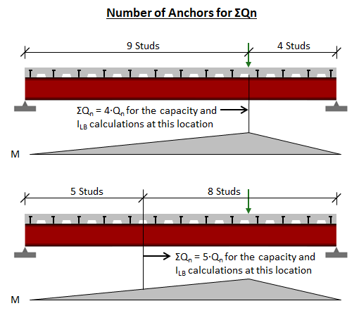
The composite beam capacity is determined at each offset along the member that falls in a positive moment region. The minimum number of steel anchors from the offset location to the point of zero moment in either direction (denoted as "effective studs" in the design output) is used when calculating the positive flexural strength for the composite beam as shown in the image below. The negative flexural strength (i.e. the concrete is subject to flexural tension) is calculated according to Chapter F of the AISC 360 Specification for Structural Steel Buildings assuming that the unbraced length is equal to the member length and the lateral-torsional buckling modification factor, Cb, is equal to 1.0.
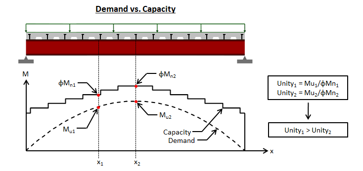
The composite beam capacity is determined at each offset along the member and compared with the demand at the corresponding offset. Since the demand and capacity vary along the length of the beam, the controlling unity value (largest demand/capacity ratio) may not occur at the point of maximum moment. The image below shows the demand vs. capacity moment diagrams for a simply supported composite beam with uniform load and a single stud region. For this case, Unity2 at offset x2 (the center of the member) is less than Unity1 at offset x1 (a location away from the center of the member). Therefore, Unity1 controls for this member. VisualAnalysis allows the spacing of steel anchors to be defined in multiple regions of the beam so that capacity of the member can be tailored to the beam's demand.
VisualAnalysis can determine both the pre-composite and composite deflections of a beam. The permanent pre-composite deflections are automatically added to the beam's composite deflections to produce the total deflection. Both the pre-composite deflections and the total deflections are compared with the user defined deflection limits.
VisualAnalysis uses the lower bound moment of inertia as described in the AISC Steel Construction Manual in calculating the composite beam deflections. The lower bound moment of inertia of the beam depends on the location of the Plastic Neutral Axis (PNA). The minimum number of steel anchors from the offset location to the point of zero moment in either direction (denoted as "effective studs" in the design output) is used when calculating the lower bound moment of inertia for the composite beam as shown in the image above. The composite deflections are determined by scaling the deflection results of the non-Construction Deflection Load Combinations by the ratio of the steel moment of inertia to the lower bound moment of inertia. For the Unshored (Approximate) Construction type, the permanent pre-composite deflections are subtracted prior to scaling since the applied dead loads are assumed to include the total dead load on the system. The composite beam deflections are determined at each offset along the member with the lower bound moment of inertia calculated at for the corresponding offset. The lower bound moment of inertia, ILB, is defined as follows (note: for negative moment regions ILB = IS):

where
As = area of steel cross section
d1 = distance from the compression force in the concrete to the top of the steel section
d3 = distance from the resultant steel tensions force from full section tension yield to the top of the steel
ILB = lower bound moment of inertia
Is = moment of inertia for the structural steel section
ΣQn = sum of the nominal strengths of steel anchors between the point of maximum positive moment and the point of zero moment to either side

The total deflections are the summation of the permanent pre-composite deflections and the composite deflections. For shored construction, the pre-composite deflections are zero, causing the total deflections to equal the composite deflections. The following image shows the pre-composite deflections, composite deflections, and total deflections for both the shored and unshored construction conditions.
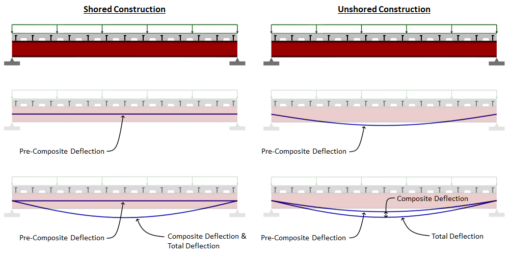
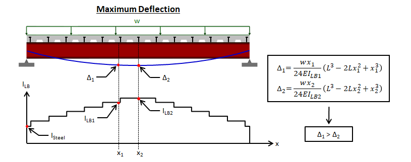
VisualAnalysis calculates the composite beam's lower bound moment of inertia at each offset along the member and calculates the corresponding deflection to compare with the deflection limit. Since the lower bound moment of inertia varies along the beam's length, the controlling (largest) deflection may not occur at the point of maximum moment or at the center of the beam. The image below shows the lower bound moment of inertia for a simply supported composite beam with uniform load and a single stud region. For this case, it is possible for VisualAnalysis to calculate Δ2 at offset x2 (the center of the member) to slightly less than Δ1 at offset x1 (a location away from the center of the member).
In addition to checking the capacity and deflection limits for composite steel beams, VisualAnalysis checks to ensure that the detailing requirements and limitations specified in Chapter I of the AISC 360 Specification for Structural Steel Buildings are met, including: material limitations, rib limitations, stud diameter limitations, stud length limitations, slab thickness limitations, and detailing requirements. Note: The steel anchor ductility checks discussed in the Chapter I Commentary of the AISC 360 Specification are not performed and should be completed by the engineer outside of VisualAnalysis.
To achieve an adequate design, the section for the members in a Design Group can be manually adjusted along with the concrete slab, deck, and anchor parameters until all the design checks pass. Note: The built in optimization feature in VisualAnalysis can be used to find an adequate steel shape for the composite beam members in a Design Group, however the concrete slab, deck, and anchor parameters must be adjusted manually as these parameters cannot be automatically optimized.
1. Create the Members
In the Model View draw or create the steel members.
2. Support the Members
Define support conditions for the model and apply the service level loads to the members.
3. Load the Members
Prior to loading the members, it should be decided which construction type is to be used for the beam-slab system. As explained above, the Construction Type is used to define the pre-composite demands (strength and deflection) for the beam-slab system. The Construction Type governs how the loads should be applied to the members and how the Load Combinations should be defined in the Load Case Manager. The following guidelines should be used for applying loads and creating load combinations for the three construction types.
4. Specify the Parameters
Select a preliminary steel Database Shape or Standard Parametric Shape and set the material properties for the beam.
5. Analysis and Preliminary Design
VisualAnalysis will automatically analyze the model and perform the appropriate design checks. Simply click on the Results View tab to view the analysis results for the model. The deflections shown in the analysis results are based on the moment of inertia of the steel beam. These results are scaled as described in the Deflections section above to account for the composite or partial composite action of the beam-slab system prior to being used for the deflection checks. Simply click on the Design View tab to see the preliminary design results. The initial design results are for a non-composite beam as the composite beam parameter is set in the tab when the Design View is activated.
6. Create/Modify Design Groups
VisualAnalysis will automatically create groups for members based on material, orientation, length, and/or cross-section. Alternatively, Design Groups can be created or modified manually as explained in the Groups Category.
7. Specify Steel Design Groups as Composite Beams
Set the Composite Beam parameter to 'Yes' for the Design Group in the Steel section of the tab. When steel design group is marked as composite beam, sections for defining the concrete slab, deck, and studs appear in the tab.
8. Specify the Construction Type
Set the Construction Type for the Design Group in the Concrete Slab section of the tab. The specified Construction Type should correspond with how the members were loaded in Step 3.
9. Define the Parameters
For each Design Group, set the parameters in the Composite Beam, Bracing (Pre-Composite), Deflections, Concrete Slab, Deck and Anchors, etc. sections of the tab in the Design View. The Bracing (Pre-Composite) section is not available for the Shored Construction Type. All of the Parameters in the tab in the Design View must be adjusted manually as VisualAnalysis does automatically optimized not these parameters. When a parameter is modified, VisualAnalysis automatically recomputes the analysis results, the design checks, and updates the Unity Ratios for the members.
10. Design the Group
Select a Design Group and manually adjust the design parameters (concrete slab parameters, deck parameters, and anchor size and layout, etc.) in the tab in the Design View and/or adjust the member's shape in the tab in the Model View until the Unity Ratios in the Design View are less than the Unity Success Limit defined in the Preferences. Note: The Design the Group button in the Design ribbon can be used to optimize the beam's shape as discussed in Steps 8-11 of the Steel Member Design Process.
The composite steel design reports in VisualAnalysis are highly customizable. To control what is included in a report, simply click on a table in the report and adjust the settings in the tab. The Extreme Rows feature is particularly useful to produce concise reports of only the controlling cases or to produce detailed reports that display every design check that is made. When this feature is set to Show All, the reports may become excessively large which can be controlled by adjusting the Conciseness feature. The reports for composite steel beam design include both a summary of the parameters input for the Design Group and tables that included the various design checks. These tables have the following columns:
| Column Name | Description |
|---|---|
| Member | The member's name. |
| Section | The member's cross-section (e.g. W8x10). |
| Offset |
This is the distance from the 'start' end of the member. The number and locations of offsets are as defined in the performance settings in VisualAnalysis. |
|
Result Case |
The result case that is used for the design check. |
| Demand/Capacity | These columns varies depending on the type of design check. In most cases these values are used directly in the unity check, but there are some special cases where the unity checks also include intermediate values or other values that not reported. |
| Code Reference | The controlling equations or provisions from the chosen design specification. For example, "G2-1" refers to the equation in the specification while a code reference like "I3.2a(a)" refers to a section in the design specification. |
| Unity Check | The unity check value for this particular member, load case, and offset. Unity checks are calculated as the absolute value of an actual force divided by an allowable strength [ASD] or as the ultimate force (factored) divided by the design strength (factored) [LRFD]. |
| Details | Intermediate values and other information which can be helpful for validating results. |