
IES VisualAnalysis User's Guide
Steel Design
VisualAnalysis performs the design of hot rolled steel members (beams, columns, braces, etc.) according to the following design specifications:
Steel members are designed for flexure (strong axis and weak axis), shear, torsion, tension, and compression to resist the varying demands along the length of the member. When necessary, the interaction of these loads are accounted for in the design checks per the selected design specification. The maximum unity value (demand to capacity ratio) for the member is shown in both the Design View and in the Report View, allowing the user to quickly identify if the member is passing (unity ≤ Unity Success Limit) or failing (unity > Unity Success Limit). In addition to checking the capacity for steel members, VisualAnalysis can check the deflection limits for the members based on the deflection limits set by the user and the Deflection Check load combinations. The shapes for steel members can be manually adjusted in the tab until a satisfactory design is reached or VisualAnalysis can automatically optimize the shape for the Design Group using the Design the Group button in the Design Ribbon. Also, the AISC Direct Analysis Method requires LRFD design checks. Composite beams can be checked using the AISC specifications.
VisualAnalysis can perform steel design using Database Shapes, Standard Parametric shapes, or custom shapes that have the required shape properties for design. For example, AISC, CSA Steel, and Euro Steel shapes can all be designed according to the aforementioned AISC and CSA design specifications while cold-formed steel shapes cannot be designed using these specifications. The IES Shape Database can be customized to include libraries of custom, foreign, or legacy shapes. The following Standard Parametric shapes are supported by VisualAnalysis for steel design: angle, channel, circle, I-shape, pipe, rectangle, rectangular tube, and tee (spandrel and zee shapes are not supported for steel design). Custom shapes can be created using IES ShapeBuilder and are supported for steel design in VisualAnalysis given the required shape properties.
Member elements can be checked for seismic compactness per the AISC Seismic Provisions (341). This check depends on the ductility requirements for the member (Non Ductile, Moderately Ductile, or Highly Ductile) and the ratio of expected yield stress to the specified minimum yield stress (Ry) which are defined by the user.
By default, the unbraced length for a member is assumed to be the member-element length between nodes. The lateral top/bottom unbraced length is used for the flexural design checks while the strong unbraced length is used for the compression design checks. See Bracing for more information on member bracing.
A variety of options are available to specify the deflection limits. To obtain deflection checks, deflection load combinations must be included in the in the Load Case Manager. More information is available on the Deflections Page.
VisualAnalysis designs steel members for flexure (strong axis and weak axis), shear, torsion, and tension according to the provisions outlined in the chosen design specification. All member forces are with respect to the member's principle axes which may not align with the geometric axes (as is the case for asymmetric shapes like single angles). When the model is sufficiently supported, loaded, and has the appropriate load combinations, the steel design checks are performed automatically. When necessary, members are checked for both their strong and weak axes and the interaction of the combined loads is accounted for according to the chosen design specification. For more information on how specific design checks are performed, see the code references for the design checks that are listed in the result tables.
All torsion checks are based on the AISC provisions. The Canadian steel code (CSA) does not provide specific requirements for torsion design (per CSA section 14.10). The general requirements given in CSA are satisfied using the more detailed requirements given in AISC 360 and AISC Design Guide 9.
The following limit states are checked in VisualAnalysis during the torsion design process:
Note: The limit state described by AISC equation H3-9 is not checked as there is no guidance for calculating Fcr in the specification.
VisualAnalysis provides two levels of torsion design.
When closed shapes are designed, limited and advanced torsion processes will produce similar results. While AISC only explicitly requires the combination of shear and normal stresses for HSS cross-sections, VisualAnalysis conservatively calculates them for all cross sections (even though they are unlikely to control) because it makes sense to do so from a mechanics viewpoint.
Torsion Boundary Conditions are idealized as one of the following during design in VisualAnalysis.
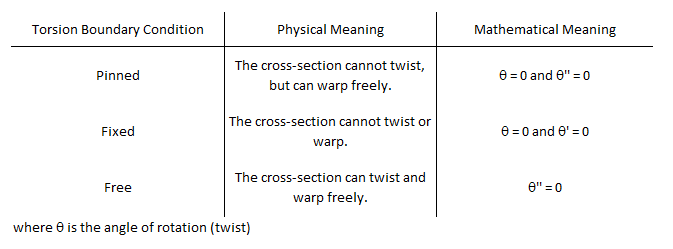
The options listed above are idealized boundary conditions. Boundary conditions between these options cannot be considered in VisualAnalysis. Furthermore, the idealized boundary condition used for design may conflict with the boundary condition used during analysis. For example, one member's twisting support may be provided by the bending stiffness of another member it frames into. In this scenario, twisting is restrained at the end and torsional moments can develop, but the rotation may still be greater than zero at the end. If during design the ends of the beam are idealized as torsionally pinned the design software will force the rotation at the ends to be zero when solving the differential equation. Sound engineering judgment must be used when selecting the appropriate boundary conditions. In some cases none of the idealized boundary conditions provided by VisualAnalysis will be appropriate, and the design will need to be completed outside of the software.
When combining stresses for torsion design, VisualAnalysis conservatively combines the maximum stresses regardless of where they occur on the cross-section. This results in conservative unity values, but is not unreasonably conservative for most shapes and loadings.
VisualAnalysis uses the following two equations to calculate unity values for the interaction of torsion with flexure and axial forces. The following equations are in their LRFD form; the ASD version is similar.
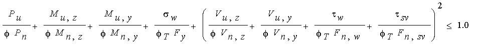
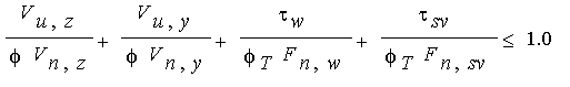
where:
"sv" denotes Saint Venant's stress
"w" denotes a stress from warping
Fn,sv = 0.6*Fy for open shapes and is defined by AISC H3 for closed shapes.
Fn,w = 0.6*Fy
fT = 0.9
The combined equations are based on AISC H3-6 and Design Guide #9 section 4.7. Combining the demands in the manner shown allows both open and closed cross sections to be checked with the same interaction equation. The AISC specification does not explicitly dictate how demands should be combined with torsion for open shapes.
The equation used to check combined stresses with torsion is more conservative than the combined equations for axial and bending found in sections H1 and H2 of AISC. Because of this AISC does not require the combined equation with torsion to be checked unless the torsion unity by itself is greater than 0.20. In VisualAnalysis a similar threshold of 0.10 is used for open shapes.
The finite element formulation for beams in VisualAnalysis does not consider warping. Warping actually has a significant impact on a beam element's twisting stiffness. Because of this, the rotations calculated during the advanced torsion design process might vary significantly from the rotations calculated during the finite element analysis.
The advanced torsion design process uses the internal torsion distribution calculated during the finite element analysis. For an indeterminate problem, this distribution may have been different if warping stiffness had been considered during the finite element analysis. In light of this, the advanced torsion design may be performed using a torsion distribution that is incompatible with the more accurate torsional stiffness used in the design calculations. Judgment is needed to determine when the incompatibility is significant or unconservative.
Torsion boundary conditions are applied at the end of each member element. As a result, segmented members must be combined before the advanced torsion design will work. The software does not prevent a chain of individual member elements from being designed. In this case, however, each element will be designed on its own and the torsion boundary conditions will be applied at the interior nodes which will lead to incorrect design results.
Several parameters must be defined to design steel members in VisualAnalysis. The design parameters are set in the tab when the Design View is selected. After creating a Design Group, choose one of the members that belongs to the group in the Design View to set up the Design Group's Parameters. Since the design parameters apply to all members in the Design Group, it is often best to choose the most conservative condition that applies to any member in the group.
| Steel |
Specification - The Design Specification used to design the members in the Design Group. Composite Beam? - Are the members in the Design Group to be designed as a composite beams? Seismic Compactness -Choose if the Design Group a member should be checked for seismic compactness according to the AISC Seismic Provisions (341). Check Constrained Axis FTB? - Should constrained axis flexural torsional buckling be checked? This feature only applies to Wide Flange members. Overstrength? - Causes the Design Group to be designed using overstrength load combinations. Live Load Reduction - If specified, design checks will only consider result cases with the matching live load reduction. Combinations with live load reduction can be created in the . Disable Checks? - Causes selected Design Group to be omitted from design checks. This feature can be used to speed up design checks and focus on targeted areas of larger models. Check Level - Determines the level of detail reported from design checks. Options are: To Failure (Fastest), Each Limit State, and All (Slowest, but provides the most information). |
| Bracing |
Lateral Top (+y) - Lateral bracing at the top side of the member (+y). Choose a bracing arrangement. Lateral Bottom (-y) - Lateral bracing at the bottom side of the member (-y). Choose a bracing arrangement. Strong (z) - Brace against strong-axis buckling for columns. |
| Torsional Bracing |
Lateral Top (+y) - Do the specified braces on the top side of the member (+y) provide torsional restraint? This is used to determine the Torsional Unbraced Length. Lateral Bottom (-y) - Do the specified braces on the bottom side of the member (-y) provide torsional restraint? This is used to determine the Torsional Unbraced Length. Strong (z) - Do the specified braces for strong-axis buckling provide torsional restraint? This is used to determine the Torsional Unbraced Length. |
| Deflections |
Strong (dy) - Specify the type of limit for beam deflections in the y-direction. Use Total to include the displacements of the nodes at each end of the element. Weak (dz) - Specify the type of limit for beam deflections in the z-direction. Use Total to include the displacements of the nodes at each end of the element. |
| Axial |
Manual Kz/Ky - Allows the user to manually override the effective length factors for the strong/weak axis. Kz/Ky Sidesway? - Choose if the member is apart of a sway frame in the specified direction. |
| Size Constraints |
Limit Depth/Width? - Allows the design search to 'Fail' if the shape is outside the Min/Max range. |
| Overrides |
Override Fy? - Override the Fy value for the material used in the design checks. This feature is useful when wanting to design using the value from the mill certification rather than the minimum value. Override Cb? - Disable the automatic determination of Cb and allows a custom value to be used. Override HSS t_des? - Override the HSS design wall thickness. Advanced Torsion - Allows the warping stresses for torsion to be calculated |
To achieve an adequate design, the section for the members in a Design Group can be manually adjusted until all the design checks pass. Alternatively, the built in optimization feature in VisualAnalysis can be used to find an adequate shape for the members in a Design Group. The optimization feature can be used to search for adequate Database Shapes or to iterate through the parameters of a Standard Parametric shape until an adequate shape is found.
1. Create the Members
In the Model View draw or create the steel members.
2. Support and Load the Members
Define support conditions for the model and apply the service level loads to the members. Set the load combinations in the Load Case Manager.
3. Specify the Parameters
Select a preliminary steel Database Shape or Standard Parametric Shape and set the material properties.
4. Analysis and Preliminary Design
VisualAnalysis will automatically analyze the model and perform the appropriate design checks. Simply click on the Results View tab to view the analysis results for the model or the Design View tab to see the design results.
5. Create/Modify Design Groups
VisualAnalysis will automatically create groups for members based on material, orientation, length, and/or cross-section. Alternatively, Design Groups can be created or modified manually as explained in the Groups Category.
6. Define the Parameters
For each Design Group, set the steel parameters (design specification, seismic compactness, overstrength, etc.) in the in the tab in the Design View. Also, adjust the bracing, deflections, axial, size constraints, and overrides for the design group as needed.
8. Design the Group
After selecting a steel design group, click the Design the Group button in the Design ribbon. In the Design Selection dialog box, choose the search type (Database or Parametric) and set the number of shapes to be returned from the optimization. For a database search, choose which database is to be searched and the category of shapes that are to be searched within the database. Also, set the size constraints if needed. For a Parametric search, select the parametric type (I-Shape, Angle, Channel, etc.) and specify the search range (Start and End) and the Increment for each parameter of the shape or choose to hold the parameter constant. Once the search parameters are set, click the Optimize Now button to search for various sections and display the unit value for each shape. If a warning stating "demands could not be satisfied" appears, then all the shapes within the search parameters have a unity value larger than the Unity Success Limit defined in the Preferences. Enabling the Return all Shapes feature will provide information on every considered section which may be useful for determining why a section failed or was not optimal.
9. Select a Section
Once the optimization is complete, select a section from the list and click the Accept Design button. Now the unity value for all members in the design group are displayed using the selected section. The tilde symbol (~) in front of the unity value indicates that the unity checks must be validated with another analysis since the member stiffness and resulting load distribution may have changed.
10. Synchronize Design Changes
Click the Synchronize Design button in the Design ribbon to automatically update the model with the new cross-section, re-analysis the model with the new member stiffness, and rerun the design checks with the updated analysis results.
11. Verify Unity Ratios
The final step in the design process is to verify that Unity Ratios in the Design View are less than the Unity Success Limit defined in the Preferences. If member sizes were drastically changed during the design process, final unity ratios can differ from predicted unity ratios because the analysis results may vary significantly.
The steel design reports in VisualAnalysis are highly customizable. To control what is included in a report, simply click on a table in the report and adjust the settings in the tab. The Extreme Rows feature is particularly useful to produce concise reports of only the controlling cases or to produce detailed reports that display every design check that is made. When this feature is set to Show All, the reports may become excessively large which can be controlled by adjusting the Conciseness feature. The reports for steel design include both a summary of the parameters input for the Design Group and tables that included the various design checks. These tables have the following columns:
| Column Name | Description |
|---|---|
| Member | The member's name. |
| Section | The member's cross-section (e.g. W8x10). |
| Offset |
This is the distance from the 'start' end of the member. The number and locations of offsets are as defined in the performance settings in VisualAnalysis. |
|
Result Case |
The result case that is used for the design check. |
| Demand/Capacity | These columns varies depending on the type of design check. In most cases these values are used directly in the unity check, but there are some special cases where the unity checks also include intermediate values or other values that not reported. |
| Code Reference | The controlling equations or provisions from the chosen design specification. For example, "F1-8" refers to the equation in the specification while a code reference like "AE3-3" refers to equation (A-E3-3) in Appendix E of the manual. |
| Unity Check | The unity check value for this particular member, load case, and offset. Unity checks are calculated as the absolute value of an actual force divided by an allowable strength [ASD] or as the ultimate force (factored) divided by the design strength (factored) [LRFD]. |
| Details | Intermediate values and other information which can be helpful for validating results. |