
IES VisualAnalysis User's Guide
Concrete Beam Design
VisualAnalysis performs concrete beam design according to the following design specifications:
Beams are designed by checking the flexure, shear, and torsion capacity of the cross-section with the varying demands at numerous locations along the length of the member. The maximum unity value (demand to capacity ratio) for the member is shown in both the Design View and in the Report View, allowing the user to quickly identify if the member is passing (unity ≤ Unity Success Limit) or failing (unity > Unity Success Limit). In addition to checking the beam's capacity, VisualAnalysis checks the minimum and maximum reinforcing limits and the reinforcement spacing requirements according to the provisions of the selected design specification. The parameters for beams can be manually adjusted in the tab until a satisfactory design is reached or VisualAnalysis can automatically optimize certain parameters of the Design Group using the Design the Group button in the Design Ribbon. Design checks are only performed for load combinations that fall under the Strength (LRFD) Design Category (see Load Case Manager).
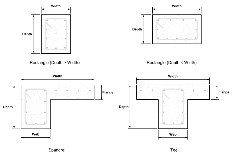
VisualAnalysis can design beams that have the following cross-sections:
These three parametric shapes are defined in terms of depth, width, flange thickness, and web thickness, as shown in the figure below.
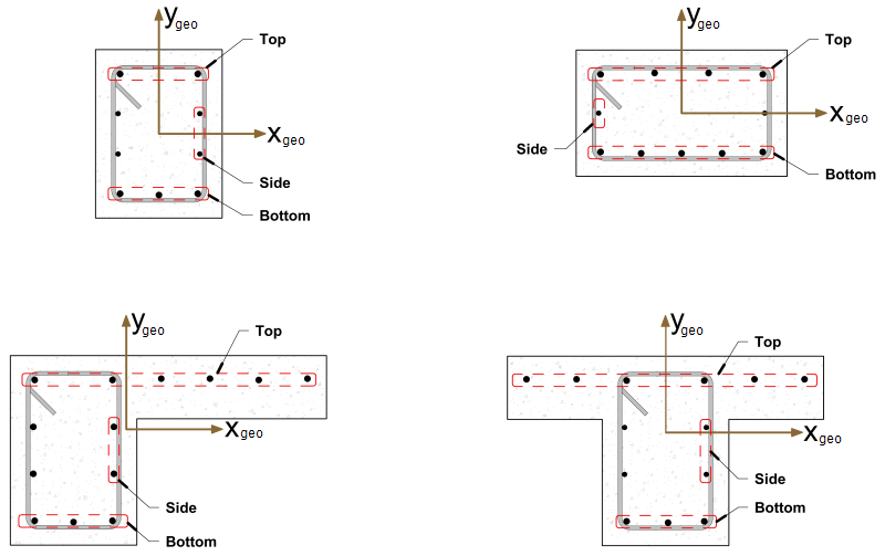
The beam's longitudinal reinforcement, is defined in the section's Geometric Coordinate System. The figure below defines the top, bottom, and side reinforcement with respect to the ygeo-axis and the xgeo-axis for the three concrete shapes available for design (the top bars are always in the positive ygeo-direction while the bottom bars are always in the negative ygeo-direction).
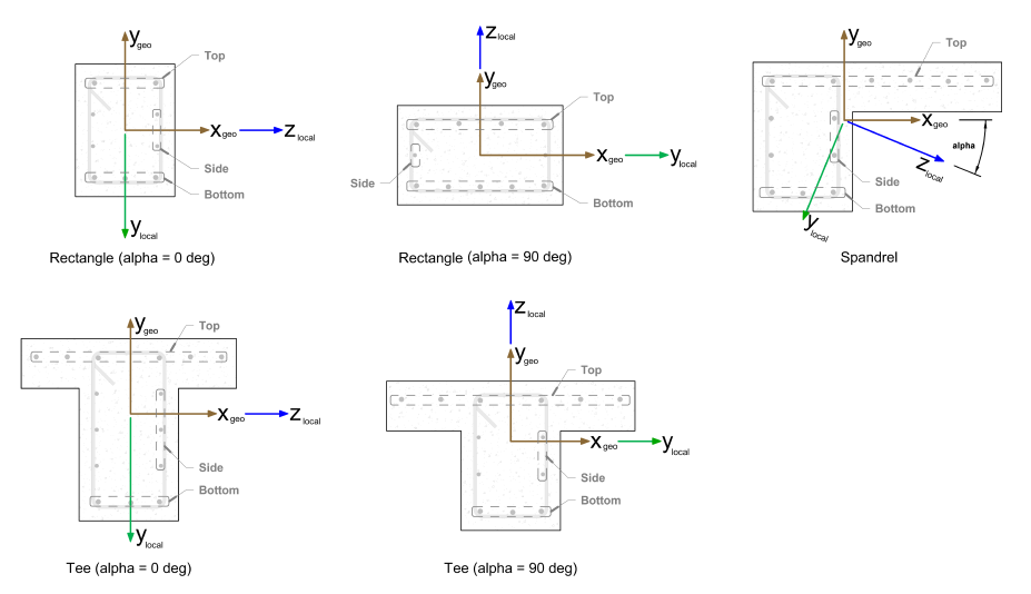
Members in VisualAnalysis are modeled such that the zlocal and ylocal axis align with the shape's major and minor principal axis, respectively. Therefore, the member's Local Coordinate System does not align with the shape's Geometric Coordinate System as illustrated below. The principle angle (alpha) is defined as the angle between the cross-section's geometric x-axis (xgeo) and the major principal axis (zlocal) where a counter-clockwise rotation is positive. The figure below shows the principle angles for the various concrete beam cross-sections. Using the principle angle and member's local axis orientation, it can be determined which edge of the beam is the top and which edge is the bottom. If the beam is not oriented correctly (i.e. if the top bars do not coincide with the "top" of the building), simply adjust the Beta angle for the member. Creating a couple of simple test cases and reviewing the Unity Ratios for a given loading condition can also help determine how the reinforcement is distributed.
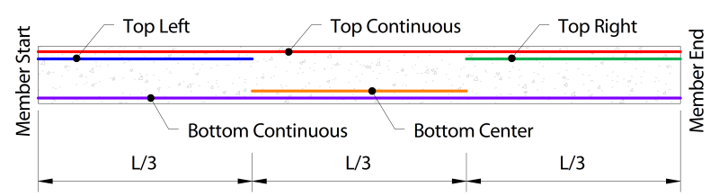
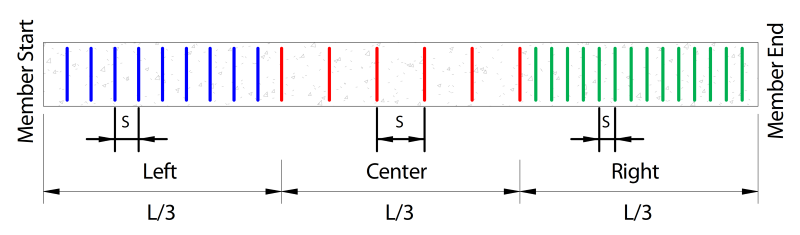
Since the demands typically vary along the length of a beam, VisualAnalysis divides beams into three segments and allows both the longitudinal and transverse reinforcement to vary in each segment as shown in the figure below. The longitudinal bars are assumed to be fully developed at the start and end of each segment. Depending on the spacing constraints of the design specification, the top and bottom longitudinal bars will be placed in either one or two layers and the distance from the extreme compression fiber to the centroid of the longitudinal reinforcement will be adjusted in the calculations accordingly.
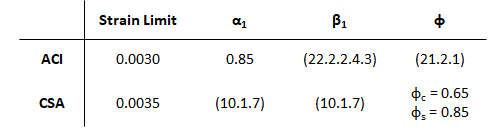
VisualAnalysis uses strain compatibility, equilibrium, the elastic-perfectly plastic constitutive law for steel, and the Whitney rectangular stress distribution for concrete to determine the flexural capacity of beams. In determining the flexural capacity of a beam, the ACI and CSA design specifications use slightly different values for the maximum concrete compression strain, the ratio of average stress in the rectangular compression block to the specified concrete strength (α1), the ratio of depth of rectangular compression block to depth to the neutral axis (β1), and the strength reduction factor (φ). The following table shows the values for these limits or provides the applicable code reference.
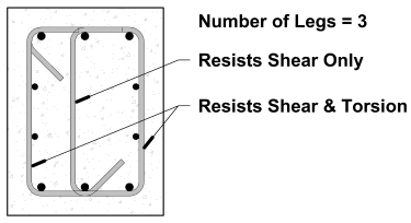
VisualAnalysis designs beams for one-way shear where the effects of axial load on the beams are not considered. VisualAnalysis ensures that the minimum transverse steel area and spacing requirements are met, along with the limits of the cross-section for torsion. Furthermore, VisualAnalysis checks the shear and torsion capacity of beams at numerous locations along the beam and reports the maximum unity value (defined as the demand divided by the capacity) for the member. When the number of legs of transverse bars exceeds two (as shown in the figure below), VisualAnalysis assumes that only the two outer legs of the transverse reinforcement resist torsion while all legs of the transverse reinforcement equally resist shear.
The β and θ parameters for shear and torsion design are determined using the General Method outlined in the CSA specification. In this method, the longitudinal strain at mid-depth of the cross-section, εx, is computed accounting for the influence of flexure, shear, and torsion. When the cross-section contains at least the minimum transverse reinforcement, the equivalent crack spacing parameter, sze, is taken as 300 mm. Otherwise, sze is calculated with sz = dv and ag = 0, conservatively. The side bars on flexural tension side of the cross-section are accounted for in the calculation of the effective shear depth, dv. Since β and θ are a function of the factored design moment, shear, and torsion which tend to vary along the length of the beam, the shear and torsion capacity can also vary along the beam's length even when the reinforcement remains constant. Therefore, the unity value is checked at numerous locations along the length of the member and the maximum value is reported. In addition to checking the capacity of the beam, VisualAnalysis checks the various detailing requirements in the CSA specification including the proportioning of the longitudinal reinforcement on the tension side and the compression side.
Several parameters must be defined to design a concrete beam in VisualAnalysis. The design parameters are set in the tab when the Design View is selected. After creating a Design Group, choose one of the members that belongs to the group in the Design View to set up the Design Group's Parameters. Since the design parameters apply to all members in the Design Group, it is often best to choose the most conservative condition that applies to any member in the group.
| Concrete |
Specification - The Design Specification used to design the members in the Design Group. High Seismic? - (ACI Only, Use Reduced φ Factors for Members Resisting Earthquake Effects) Enabling this parameter lowers the φ factors as indicated by ACI 318 Section 21.2.4 for members that are designed to resist earthquake effects and are part of a structure that relies on special moment resisting frames or special structural walls to resist earthquake effects. VisualAnalysis relies solely on this parameter in determining whether or not to use reduced φ factors (it does not attempt to calculate whether the shear capacity is greater than the shear corresponding to the development of the nominal flexural strength of the member). Only shear φ factors are influenced by this parameter for design according to the ACI specification. Member Type - Indicates the design shape (Beam or Column). Overstrength? - Causes the Design Group to be designed using overstrength load combinations. Live Load Reduction - If specified, design checks will only consider result cases with the matching live load reduction. Combinations with live load reduction can be created in the . Disable Checks? - Causes selected design group to be omitted from design checks. Check Level - Determines the level of detail reported from design checks. Options are: To Failure (Fastest), Each Limit State, and All (Slowest, but provides the most information). |
| Beam Details |
Beam Spacing - The perpendicular spacing between beams (centerline-to-centerline). This is used for Spandrel and Tees to determine the effective flange width and is not necessary for beams with rectangular cross sections. The effective flange width used for design is the minimum of the code calculated value for effective width and the actual width of the parametric tee or spandrel shape. Start/End Column Widths - Widths of supporting columns at start and end of beam. These widths are used for determining where critical moment, shear, and torsion are at the ends of the beam. The critical demands are taken at the face of the column since member's effective depth significantly increases once the column is reached. These ends correspond to the member's local axes, where the local x-axis goes from the start-node to the end-node. Note that the critical section for shear can be taken "@ d" from the face of the support using the "Shear "@ d" from start/end" parameter (below). Shear "@ d" from start/end - When enabled, the shear value calculated "@ d from the face" of the support is used for the shear and torsion checks when the check location is between the face of the support and d. Note that when using the CSA design specification, "dv" is used instead of "d". Use Metric Bars - Should metric reinforcement be used instead of imperial bar sizes? |
| Reinforcement |
Main Fy - Specified yield strength of the longitudinal reinforcement in the beam. Top Reinforcement - The size and quantity of Top reinforcement throughout the beam. Bottom Reinforcement - The size and quantity of Bottom reinforcement throughout the beam. Side Reinforcement - The size and quantity of Side reinforcement throughout the beam per each side. Note side bars are not used to resist flexure. Stirrup Fy - Specified yield strength of the stirrups in the beam. Stirrup Size - The size of transverse reinforcement. Number of Legs - The number of legs used for shear reinforcement. Are Stirrups Closed? - Are closed stirrups used throughout the section? Spacing - The center-to-center spacing of the stirrups. A different stirrup spacing can be specified for each 1/3 of the beam length. A spacing of 0 means no stirrups are provided. Top Cover - Concrete clear cover at the top of the section. Calculated as the distance from the top of the stirrup to the top of the section. Bottom Cover - Concrete clear cover at the bottom of the section. Calculated as the distance from the bottom of the stirrup to the bottom of the section. Side Cover - Concrete clear cover at the side of the section. Calculated as the distance from the side of the section (or web in the case of Tee and Spandrel shapes) to the stirrup. |
| Deflections | Strong/Weak - Specifies the type of limit for normal beam deflections. |
| Size Constraints | Limit Depth/Width? Allows the design search to 'Fail' if the shape is outside of the Min/Max range. |
To achieve an adequate design, the Design Group's Parameters can be manually adjusted until all the design checks pass. Alternatively, the built in optimization feature in VisualAnalysis can be used to iterate through some of the beam parameters to find an adequate solution using the following process:
1. Create the Beams
In the Model View draw or create the concrete beam members.
2. Support and Load the Beams
Define support conditions for the model and apply the service level loads to the members. Set the strength design load combinations in the Load Case Manager.
3. Specify Preliminary Parameters
Set the preliminary beam shapes, dimensions, and material properties. Note that concrete beams must have Standard Parametric cross-sections and all concrete beams in a Design Group must have the same shape and dimensions.
4. Analysis and Preliminary Design
VisualAnalysis will automatically analyze the model and perform the appropriate design checks. Simply click on the Results View tab to view the analysis results for the model or the Design View tab to see the design results. VisualAnalysis uses default parameters for concrete beam reinforcement that will likely need to be adjusted (see Step 7).
5. Create/Modify Design Groups
VisualAnalysis will automatically create groups for members based on material, orientation, length, and/or cross-section. Alternatively, Design Groups can be created or modified manually as explained in the Groups Category.
6. Concrete Parameters
For each Design Group, select the appropriate design specification, member type, seismic & overstrength parameters, etc. in the in the tab in the Design View.
7. Define Reinforcement
Manually adjust the reinforcement in the tab in the Design View. The layout, size, quantity, and yield strength of the longitudinal bars can be set while the size, spacing, and yield stress of the member's transverse bars can be set. Upon changing the reinforcement for a Design Group, the unity checks are automatically updated in the Design View.
8. Design the Group
After selecting a concrete beam design group, click the Design the Group button in the Design ribbon. In the Design Selection dialog box, choose a parametric type and set the constraints on the dimensions for the cross-section of the concrete member. Click the Optimize Now button to search for various sections and display the unit value for each section using the reinforcement that was defined in the previous step. Note that VisualAnalyis does not vary the reinforcement for each section and only optimized the size of the parametric shape. If a warning stating "demands could not be satisfied" appears, then all the sections within the search parameters have a unity value larger than the Unity Success Limit defined in the Preferences. Enabling the Return all Shapes feature will provide information on every considered section which may be useful for determining why a section failed or was not optimal.
9. Select a Section
Once the optimization is complete, select a section from the list and click the Accept Design button. Now the unity value for all members in the design group are displayed using the selected section. The tilde symbol (~) in front of the unity value indicates that the unity checks must be validated with another analysis since the member stiffness and resulting load distribution may have changed.
10. Synchronize Design Changes
Click the Synchronize Design button in the Design ribbon to automatically update the model with the new cross-section, re-analysis the model with the new member stiffness, and rerun the design checks with the updated analysis results.
11. Verify Unity Ratios
The final step in the design process is to verify that Unity Ratios in the Design View are less than the Unity Success Limit defined in the Preferences. If member sizes were drastically changed during the design process, final unity ratios can differ from predicted unity ratios because the analysis results may vary significantly.
Design reports are available by double-clicking on a member in the Design View, by selecting a member and clicking the Report Selected button in the right-click context menu, or by adding tables individually from the Report View. The Concrete Beam Parameters used for the Design Group are available with the Member Design Results table by clicking in the table and enabling the Include Parameters setting in the tab.