
IES VisualAnalysis User's Guide
Member Elements
VisualAnalysis members consist of 2-node prismatic (or linear depth-tapered) line finite elements. These elements can be used to model frame or truss members. For member elements, the axial displacements are based on a linear displacement assumption and the transverse displacements are based on a cubic displacement assumption. Shear effects are included only for user-defined sections with nonzero shear areas. Special cases such as end zone are all handled internally using multiple member elements (creating a combined member). Select one or more members to view or edit the member properties in the tab.
Members can be created using the command to draw members on a Grid or to existing nodes in the model. Also, the command can be used to make members based on a the start and end coordinates which can be input by the user or defined by existing node. After members are created, they can be Extended, Trimmed, Merged, or Split using the commands in the Actions section of the Structure tab in the Ribbon as defined below.
In VisualAnalysis, a Global Coordinate System is defined for each project, a Local Coordinate System is defined for each member, and a Geometric Coordinate System is defined for each shape. This section discusses the difference between these coordinate systems and how they are related. To understand how members are oriented in a project, it is useful to turn on the Local Axes, the Axes (global), and the Picture View and in the tab.
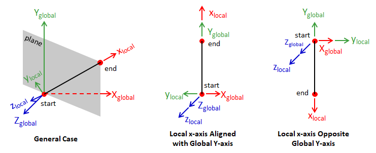
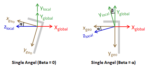
In VisualAnlysis, member's local coordinates are always represented with lower case letters {x, y, z} whereas global coordinates are represented with upper case letters {X, Y, Z}. The local coordinate system aligns with principal axes of the member's assigned shape and is used to define loads, end releases, and results. When a member is created, the local x-axis is defined from the start node to the end node and the local y-axis typically lies in the plane formed by local x-axis and a vector parallel to global Y-axis (see the figure below). When the local x-axis aligns with the global Y-axis, the local y-axis is opposite the global X-axis and when the local x-axis is opposite the global Y-axis, the local y-axis is aligns with the global X-axis (see the figure below). The local z-axis is defined from the local x-axis and y-axis using the right-hand-rule. The local coordinate system for a member can be reversed using the command (the start and end nodes are simply swapped).
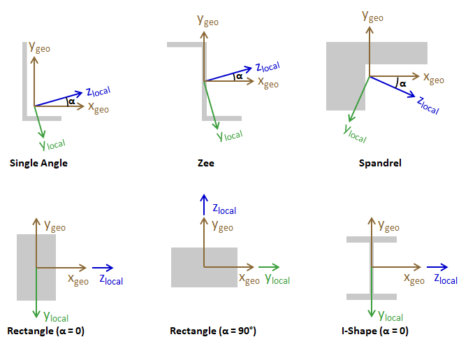
The shapes used to define members in VisualAnalysis have a Geometric Coordinate System (xgeo and ygeo) as shown for several shapes in the figure below. For parametric shapes, the Geometric Coordinate System is shown in the Parametric Shape Dimensions dialog box in VisualAnalysis. Members in VisualAnalysis are modeled such that the zlocal axis and the ylocal axis align with the shape's major and minor principal axis, respectively. Therefore, the member's Local Coordinate System does not align with the shape's Geometric Coordinate System as illustrated below. The Principal Angle (alpha) is defined as the angle between the cross-section's geometric x-axis (xgeo) and the major principal axis (zlocal) where a counter-clockwise rotation is positive. The Principal Angle is zero or 90 degrees for symmetric cross sections. For asymmetric shapes (e.g. single-angles, zees, spandrels, etc.), the shape's principal axes do not align with the geometric axes. When the Principal Angle is non-zero, it is displayed in the tab. The figure below shows the principle angles for the various cross-sections.
The shape for a member is defined on the tab when one or more members is selected. There are five types of shapes available for use in VisualAnalysis: Database Shapes, Standard Parametric Shapes, Custom Shapes, Analysis Blobs, and Rigid Links. Custom Shapes are created in IES ShapeBuilder and added them to the CustomShape Database.
IES includes a large Shape Database of steel, wood, aluminum, cold-formed, and other shapes common in the USA and some other countries. The database is customizable using IES ShapeBuilder, but cannot be modified directly using VisualAnalysis. Selecting a database shape will typically also define material and therefore it is best to define the shape prior to defining the material. The shape database contains Virtual Joists and Virtual Joist Girders which are developed by the Steel Joist Institute. Their website has information on the basic concept and purpose. You may create models with these shapes and get design-checks as if they were steel beams (please understand their purpose and limitations before using them).
Parametric shapes are defined by dimensions such as width, depth, and thickness, which are input by the user. Parametric shapes are commonly used for defining concrete members (e.g. square, rectangle, round, etc.). In general, parametric Shapes are supported for design checks, however, there are some limitations. VisualAnalysis offers the following types of parametric shapes: Angle, Channel, Circle, I-Shape, Pipe, Rectangle, Rectangular Tube, Spandrel, Tee, and Zee.
Custom Blobs are a quick way to defined the numerical properties of a shape that are needed to perform the analysis (the actual dimensions of the shape are not defined). Custom Blobs are only available in the project in which they were created (i.e. they are not added to the shape database). Use Custom Blobs with care as the shape properties are not checked other than to ensure they are positive. Custom Blob members have many limitations including they cannot be tapered or used for design (except for Generic Deign Groups).
Rigid links are a short, stiff member element used to connect two nodes at some offset and to control the transfer of forces between elements framing into those nodes. By changing a member into a rigid link, VisualAnalysis will automatically take care of the member's stiffness. End releases are the only parameter that can be defined by the user for rigid links.
The tab shows the types of shapes available in the Source drop-down list: Standard Parametric, Database Shape, Rigid Link, <Add Custom 'Blob'...>, <ShapeBuilder>, followed by a list of shapes that are already used or have been recently used in the project. Use this list to quickly find a shape for a new member element.
Material properties come from the IES material database, which includes the most common structural materials. Materials for selected elements are set in the tab. All materials in VisualAnalysis are linear, elastic, and isotropic. Select a shape before selecting a material as most database categories have a default material that will be automatically assigned the shape is selected (i.e. if the material is specified first, it might get replaced). If the database does not contain the desired material, simply create a custom material. Note: The Weightless parameter can be used to include or exclude the weight of particular element(s) in the analysis.
Add custom materials by clicking the button in the Material Database dialog box. Specify the material "type" to define custom materials categorized as wood, steel, concrete etc. that will work for the corresponding design checks. After selecting a material type, defining properties as needed or use the default values. If some of the defining properties for a material type are unknown, consider using a General material type where only four basic material properties need to be defined: the modulus of elasticity (E), Poisson's ratio (Nu, n), the weight density (Gamma, g), and the coefficient of thermal expansion (Alpha, a). The Shear Modulus, G, is calculated internally as: G = E / (2*(1 + Nu)).
The torsional, axial, and flexural stiffness of selected members can be factored in the tab to increase or decrease the stiffness of the members in the model. Adjusting the stiffness of the members allows the user to easily analyze concrete members using cracked moments of inertia, analyze steel members with reduced stiffness to account for residual stresses, etc.
In VisualAnlyasis, member connections in a Space Frame model are rigid by default (i.e. full force and moment transfer exists between the member, the joint itself, and all other members with rigid connections framing into the joint). Member releases are always specified in the member's Local Coordinate System. Depending on the connection, members In reality are not always capable of transferring certain forces or moments at their ends. For example, a steel beam connected to a column with a simple shear connection is not capable of transferring large moments to the column. To model this situation, a moment release should be used at the end of the beam. Use the tab to adjust the Connections and Releases for the selected members in the model. The following common Connection Types can be selected from the drop down menu to automatically populated set the Releases for the member.
The Simple Connect connection types is commonly used to model truss members (keep in mind that truss members can still experience moment when loaded between the nodes). For more complicated conditions, automatically set the Releases for each end of the member and the Connection type will automatically switch to <See Releases>. Force releases can be used in situations where force cannot be transferred in a particular direction (e.g. due to slotted holes in a steel connection). When a connection cannot be defined as Rigid or Released (e.g. for a partially restrained moment connection), use the Semi Rigid options in the tab to specify the stiffness of the connection for strong or weak bending. When a member is selected, the member releases are shown in green at the end of the member.
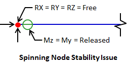
When releases are incorrectly used the model can become unstable and VisualAnalysis will not be able to perform the analysis. One common mistake is for a Simple Connection to be used at a pinned support as shown in the figure below. For this case, the node can spin in the model since the support provides no rotational support and the member only provides rotational support about the local x-axis (since Mx = rigid). For more on stability issues, see My Model is Unstable.
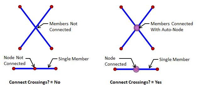
When enabled, the Connect Crossings feature allows members to automatically connect to any element or node that crosses the member (when no node is present at the crossing, an auto-node will be created as shown in the image below). When the Connect Crossing feature is disabled, no force will be transferred between the member and the crossing element. When two members cross, the Connect Crossings feature must be enabled for both members for the connection to be made. Tension Only and Compression Only members do not have the Connect Crossing feature. Crossing Connections can be shown or hidden in the model in the Member Details section of the tab.
If a member is not oriented correctly in the model (i.e. if the top of the shape do not coincide with the "top" of the building), simply adjust the Beta angle for the member in the tab. The Beta Angle changes the orientation of the local coordinate system by rotating the section about the local x-axis (positive rotation follows the right-hand-rule). By default, the Beta Angle for asymmetric members is set equal to the Principal Angle (alpha) so that the geometric axes align with the global coordinate system as shown below. Understanding the shape's orientation is crucial for understanding the analysis results of a member and for performing member design. Understanding the shapes orientation is also vital when defining the reinforcement for Concrete Beams.
When selected, members in VisualAnalysis can be set to behave as Tensions only, Compression only, or Normal (2-way) in the Options section of the tab. By default, members are set to Normal (2-way). Note: A tension-only member is different from a cable element, which sags and can have pretension. Slender bracing members such as a rod that will buckle under a small axial compression are modeled as tension-only members. In some cases, one way behavior is not permitted such as:
Each member is designated as one of three framing types (Beam, Column, or Bracing). The framing type is automatically set for members based on the vertical axis setting and the orientation of the member when it is created (changing the orientation of the member after it is created will not cause the framing type to change). Select a member to change its the framing type in the Options section of the tab. A member's framing type impacts the following:
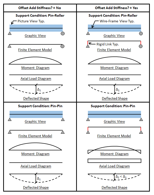
Member offsets affect members visually and can also increase the stiffness of the member in the model. To offset a member, select the member in the Model View, choose the Offset Coordinates, and specify the offset values. By default, the Offset Add Stiffness? parameter is disabled in the Project Settings and offsetting members only influences the model visually. It is important to remember that while the picture view shows a 3D image of the member, the member is modeled with a line element. When the Offset Add Stiffness? parameter is enabled, the line element is offset and rigid links are used to accommodate the offset. Boundary conditions can have a significant effect on member forces when offsets are used to add the stiffness to the model. It is important to always validate the analysis results prior to designing members in VisualAnalysis, especially when using offsets to increase the member's stiffness. The figure below summarizes how the Offset Add Stiffness? parameter affects member forces with various boundary conditions when member end offset exist.
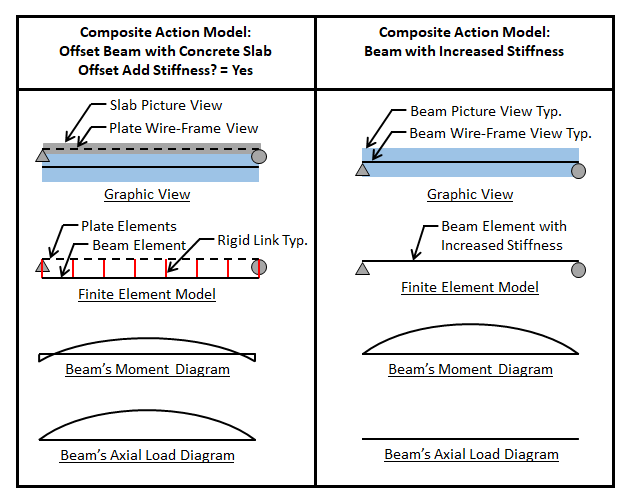
Member offsets are commonly used to model the increased stiffness that results from composite action between steel beams and concrete slabs. When the beam is offset in these systems and the Offset Add Stiffness? parameter is enabled, rigid links connect the beam element to the plate elements as shown in the figure below. While this model can approximate the stiffness of the composite system for positive bending (i.e. the concrete slab is in compression), the forces in the beam element may not accurately represent the forces for the composite system (e.g. significant axial forces may be present in the beam and the moment may be underestimated for composite design). When using this approach, the analysis results from the composite system may not be suitable to design the composite beam in VisualAnalysis. Alternatively, the increased stiffness of the composite or partially composite system can be accounted for in the model by applying a stiffness factor to the beam element without explicitly modeling the slab. This method allows the stiffness to be increased without creating an undesirable force distribution in the member. Care should be used when modeling composite steel beams with negative moments (i.e. the concrete slab is in tension) as cracking of the concrete can lead to significant changes in the stiffness of the composite section which are not accounted for in the model. Note: To effectively use the Composite Steel Beam design module for both strength and deflection checks, only the steel member should be modeled. The stiffness from the concrete slab or from member offsets should not be included in the model as these will be automatically accounted for in the design checks.
The Beam Top @ Nodes project setting causes all the beams in the project to be offset in the vertical direction by half their depth (nodes are at the 'top' of the member). When the Offset Add Stiffness? parameter is disabled, this setting only influences the beam's location graphically. When the Offset Add Stiffness? parameter is enabled, this setting influences the beam's location graphically and influences the stiffness of the beam as explained in Member Offsets. When the Beam Top @ Nodes parameter is enabled, the option is also given to ignore the manually specified y-direction beam offsets using the Ignore Beam Offsets parameter.
VisualAnalysis allows members to have a single or double linear depth variation along the length of a member. The defined shape of the member is the starting depth (Depth 1) and the Depth 2 is the value input by the user to define the end of the taper offset. The stiffness of the member is calculated using the depth of the member at any point along the member's length. The Start Fraction x and End Fraction x offsets (measured from the starting node for the single-taper, and from both ends for the double-taper) can be adjusted to specify the location where the taper begins and ends. By default the offsets are set to zero and the Depth 2 is at the member's end node. The centerline, bottom, top specification for taper type affects the members graphically but does not affect the member's stiffness.

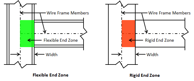
By default, connections in VisualAnalysis are modeled at the centerlines of the members. End zones (also know as panel zones) can be modeled in the program using the End Zones feature in the tab for selected members. For structural steel moment connections, panel zone has some flexibility which can be modeled. When a concrete beam frames into a stiff wall or column, it may be desired to model the end zone as rigid. To specify end zones enter the Width (the distance along the length of the selected member) of each end zone and set the End Zone to Flexible or Rigid. Internally, VisualAnalysis creates a member of the specified length at the end of the selected member and adjusts the stiffness of the member accordingly. When Flexible is selected, a percentage of the member stiffness is specified to be used for the end zone. When rigid is selected, VisualAnalysis uses a multiplier of 1000 on the member stiffness to determine the end zone member stiffness.
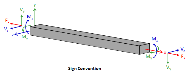
Local member forces using the following sign convention:
Axial stress (fa), bending (fb), and combined axial and bending stresses (fc) are reported for members in VisualAnalysis. Shear and Torsional Stresses are not calculated in VisualAnalysis but can be found using IES ShapeBuilder.

Member displacements in the global coordinate system can be seen in the Result View by selecting an individual member and viewing the results in the tab, or by creating a Member Displacement report table and displaying the global displacement columns.