Requires: Advanced Level
Introduction
The script feature in VisualAnalysis is a powerful tool used to create models objects, generate service cases, apply loads, extract results, etc. using a command line interface. In addition to supporting the various Commands outlined in this Help File, the command line will accept any valid command in the C# Programming language (allowing the use of if statements, for loops, etc.). In addition to using the command line directly, more complex Scripts can be generated in any text file and read into the program. This allows models with complex geometry to be created, parametric studies to be performed, finite element meshes to be automatically refined until convergence, etc.
Command Line Basics
- Location
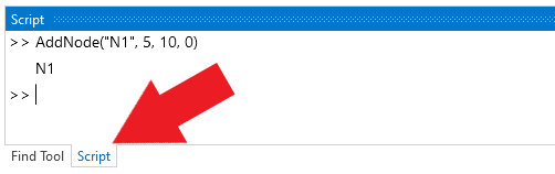
- The Script tool is accessed by selecting the script tab at the bottom of the Find Tool. By default, the Script will replace the Find Tool when selected, but the two can be floated and docked independently if needed.
- Units
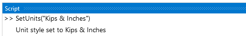
- Input and output are always in the current unit style. The style can be changed from the command line.
- Add Nodes
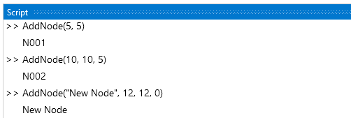
- Add nodes to the model by entering the 2D or 3D location. A node name can be optionally defined. Note: Node and other item names must be enclosed in quotes.
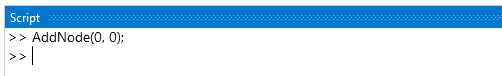
- The return value can be suppressed by using a semi-colon on at the end of the command.
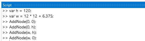
- Information can be stored in variables and math can be performed in the command line. Variables circumvent the need to input the same number repeatedly. The example below uses variables and math in the command line to define the geometry of a frame that is 10 feet tall and 12 feet - 6 3/8 inches wide (assuming the current unity style is Kips & Inches). Note: When storing a value in a variable, the line must end with a semicolon.
- AddMembers
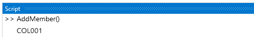
- Selection: A member can be created by selecting two nodes graphically and then entering the AddMember() call.
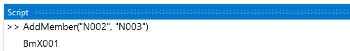
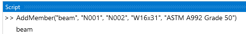
- Specification: A member can also be created by using the names of two existing nodes. Note: When using the specify option, the name of the item (nodes in this example) must be enclosed in quotes.
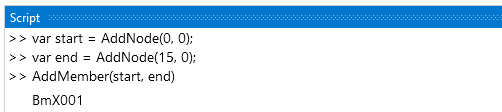
- For convenience, nodes can be stored in variables and then the variables can be used to define the member.
- Once the member is added, it will be selected, and its properties can be modified in the Project Manager as usual. Alternatively, most of the member properties can be defined when adding the member from the command line. Several options are available, see the Commands page for a complete list.
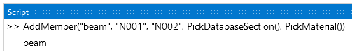
- The PickMaterial(), PickDatabaseSection(), or PickParametricSection() calls can be used to set the material or cross-section when their exact name is unknown. These command calls bring up the material or shape dialog box and then return the name of the selected item.
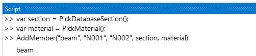
- The PickMaterial(), PickDatabaseSection(), or PickParametricSection() calls can also be used to set variables which can then be used when adding members.
- Set Boundary Conditions
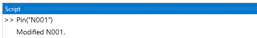
- The Pin(node), Fix(node), and Free(node) call can be used to set standard boundary conditions.
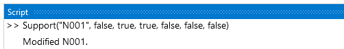
- The Support(name, DX, DY, DZ, RX, RY, RZ) call can be used to set custom boundary conditions for a node where false = free and true = fixed. Note: Boolean values (true and false) must be lower case and should not be enclosed in quotes.
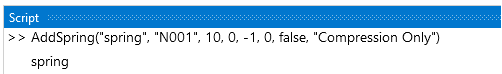
- Translational or rotational spring supports can be added using the AddSpring(name, node, k, X, Y, Z, isRotational, action) call.
- Apply Loads
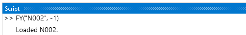
- Individual nodal forces or moments can be applied to selected or specified nodes in the current service case using the FX(magnitude) and MX(node, magnitude) and similar calls. Note: Use a negative magnitude to apply loads in the negative global direction.
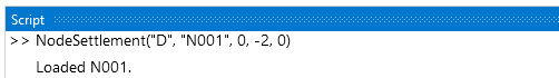
- Multiple nodal forces, moments, settlements, or rotations can be applied to nodes using the calls outlined on the Commands page. Note: Settlements and rotations may act only in the direction of a fixed support as usual.
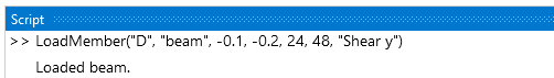
- A variety of options are available to apply loads to members using the command line as outlined on the Commands page. In the example below, member Bm1 is loaded in the D service case with a linearly varying force of -0.1 to -0.2 kip/in about the member's local y-axis between 24 and 48 inches (assuming the current unity style is Kips & Inches).
- Obtain Results
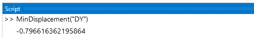
- The maximum or minimum displacement for a specified degree of freedom across all result cases or for a specified result case can be obtained using command line.
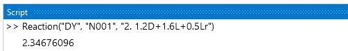
- The displacement or reaction for a specific node can be obtained for a particular load case or the maximum or minimum value across all load cases can be extracted using the true or false Boolean value, respectively. For more information, see the Commands page.
- Miscellaneous
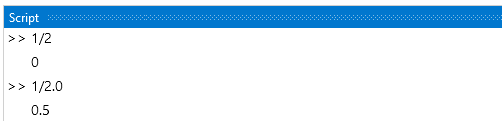
- Integer Math: In the command line, the quotient of two integers is an integer which may not produce the intended result. See the C# Numeric Types Tutorial for more information.
C# Programming
The command line accepts any valid command in the C# Programming Language, allowing the use of if statements, for loops, etc. In the example below, a command is defined to describe the y coordinate of a circle in terms of x. The Sqrt(Double), and Pow(Double, Double) methods of the .Net System Math Class are used to perform the square root and squared operations for the command, respectively. For loops are then use to add nodes to the model and to add members connecting the nodes.
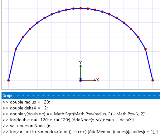
The programming for the arch in the image above could be refined to generate a model with equal member lengths along the arch. This would require more advanced programming that would be better suited for an External Script. See the Catenary Arch Example.
