Column-Piers elements in VisualFoundation are used to apply vertical loads, sliding forces, and moments to foundations at a specified location.
Piers are defined by their location, size, shape, height, and material properties. Four shapes are available: Square, Rectangular, Circular and Octagon. The radius of an octagon pier is based on the octagon being inscribed inside a circle with the specified radius. Note: In the Finite Element Analysis (FEA) model, a pier loads a single node in the slab's mesh; therefore, care should be taken when specifying column piers with large cross-sections.
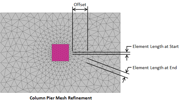
The FEA method is approximate and the accuracy of the FEA solution typically increases as the mesh becomes finer. Generally, a finer mesh should be used in regions where there are large changes in stresses in the plates (such as at piers where concentrated loads can create stress concentrations). Select a pier(s) and set Refine? = True in the tab to refine the mesh in the regions of the chosen pier(s). The mesh refinement parameters for piers are defined in the image below.

Vertical forces (compression and tension), in addition to sliding forces and moments in two directions can be applied to piers. The pier's self weight can be included by checking the option for the selected pier in the tab. The sliding forces are assumed to act at the top of the pier and will generate moments in the slab. Sliding forces are also used for the sliding checks on the foundation.
During the finite element analysis each pier is modeled as a member element cantilevered from the slab mesh. Loads are applied to the top of the pier. Piers are assumed to be unsupported over their entire length.
Only concrete piers can be designed in VisualFoundation and no other material can be specified for piers. VisualFoundation checks and designs concrete Piers according to the following design specifications:
Pier reinforcement (longitudinal and transverse) is specified in the Foundation Design view for the selected pier(s). The following limit states are checked:
Note: VisualFoundation does not design a piers when its height is set to zero (zero-height piers can be used to apply loads at the top of the slab). To preserve the legacy load definition, "columns" coming from VisualFoundation Version 8.0 and earlier are given a zero height automatically. Piers with an octagonal cross-section are cannot be designed in VisualFoundation.
According to ACI 318 Section 10.3.1.2: "For columns with cross sections larger than required by considerations of loading, it shall be permitted to base gross area considered, required reinforcement, and design strength on a reduced effective area, not less than one-half the total area." This provision allows for the reduction of the minimum required area of longitudinal reinforcement from 0.01Ag (per Section 10.6.1.1) to 0.005Ag when the column section is larger than required for design.
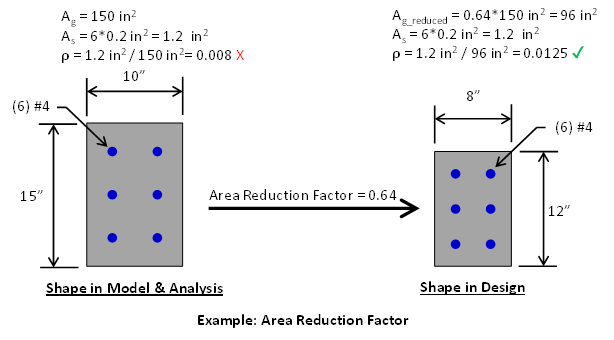
Setting the Area Reduction Factor to a value less than 1.0 causes VisualFoundation to design the Column Pier with a smaller effective cross section. For example, a 10-inch x 15-inch Column Pier (Ag = 150 in2) with an Area Reduction Factor of 0.64 will be designed as an 8-inch x 12-inch Column Pier (Ag = 8 inch * 12 inch = 0.64 * 150 inches2 = 96 inches2) reducing the gross area and, consequently, the minimum reinforcement requirements. This reduction provides greater design flexibility and can result in significant reinforcement material savings, particularly for oversized columns. Note: The size of member is only reduced in the design module it is not reduces in the finite element analysis.
Note: The Area Reduction Factor is only available for ACI design specifications. The CSA design specification also allows for the reduction of the minimum longitudinal reinforcement area from 0.01Ag to 0.005Ag, but it accomplishes this differently (refer to Clause 10.10.5), which VisualFoundation accounts for automatically.

In VisualFoundaiton, Punching Shear design checks are performed at pier locations and the program automatically determines the punching shear perimeter (critical section). An individual pier can also define punching shear reinforcement in the form of headed shear studs or shear stirrups located in the slab. Additional information regarding punching shear design checks and punching shear reinforcement can be found on the Punching Shear page of the Help File.
Reports are available to show the results for each of the applicable limit states as well as interaction diagrams for piers in VisualFoundation.