Piles in VisualFoundation are used to support the foundation at a specified location in the model.
Piles are defined by a location, cross-section, material, and length. A Pile's cross-section can be defined by standard parametric shapes or a shape can be chosen from the database. Note: In the Finite Element Analysis (FEA) model, a pile supports a single node in the slab's mesh; therefore, care should be taken when specifying piles with large cross-sections.
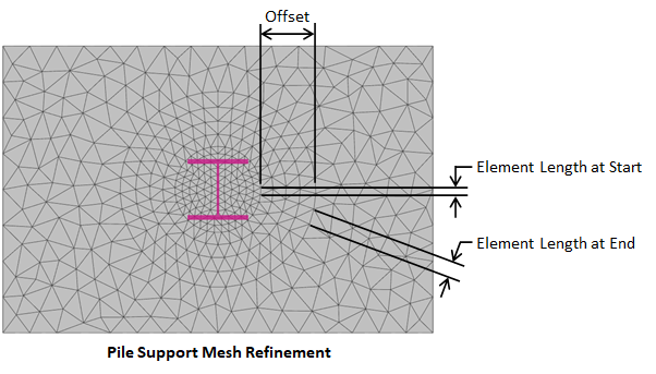
The finite element analysis (FEA) method is approximate and the accuracy of the FEA solution typically increases as the mesh becomes finer. Generally, a finer mesh should be used in regions where there are large changes in stresses in the plates (such as at piles where the support can create stress concentrations). Select a pile(s) and set Refine? = True in the tab to refine the mesh in the regions of the chosen pile(s). The mesh refinement parameters for piles are defined in the image below.

For the Sliding Stability checks, piles can be set in the to have either an infinite sliding resistance (i.e. the total sliding resistance of the foundation is infinite) or a total resistance of the piles can be manually specified. When a total pile resistance is entered, it will be added to the frictional resistance and the passive resistance when calculating the factor of safety for sliding.
Piles cannot be directly loaded in VisualFoundation. A pier can be defined at the same location as the pile (i.e. connected to the same node in the finite element model) and load can be applied to the pier.
VisualFoundation calculates the default "Rigid" stiffness for the pile as AE/L which can be overridden to specify a custom stiffness. Piles are treated as axial-only spring elements during analysis and the action can be set to two-way, compression only, or tension only. Note: There are no soil-structure considerations for piles in VisualFoundation.
In VisualFoundation, steel, wood, and concrete piles can be designed according to the following design specifications:
In VisualFoundation, the geotechnical capacity is manually specified for both tension (uplift) and/or compression. These parameters represent the force at which the soil supporting the pile fail (values are typically obtained from a geotechnical engineer or report). A unity check with either service or strength-level loads is performed to compare the actual demand against the specified capacity.
The pile design parameters (bracing, reinforcement for concrete, C-factors for wood, etc.) are specified in the tab when the Foundation Design view is active. In VisualFoundation, piles only carry axial forces and the axial demand is checked against the applicable limit state for the appropriate material and design specification chosen. Note: VisualFoundation does not consider the effects of slenderness for concrete piles. Therefore, concrete piles are designed as short columns and moment magnifiers are not used.
In VisualFoundaiton, Punching Shear design checks are performed at pile locations and the program can automatically determine the punching shear perimeter (critical section). An individual pile can also define punching shear reinforcement in the form of headed shear studs or shear stirrups located in the slab. Additional information regarding punching shear design checks and punching shear reinforcement can be found on the Punching Shear page of the Help File.
Report tables, which include intermediate details are available for each check and/or limit state.