
IES ConcreteBending User's Guide
Analysis
ConcreteBending uses finite element analysis (FEA) to determine the displacements, shears, and moments in the slab system. Exporting the model as a VisualAnalysis project () will show what is happening behind the scenes in ConcreteBending. While ConcreteBending attempts to handle many details of the FEA method, some knowledge of FEA is still required to use the program successfully.
To control the number of plate elements, pick between course, medium, fine, or specify a desired number directly in the . The actual number of meshed plates generated in the model is shown under Meshed Plates. Turn on Meshed Plates in the tab to view the meshed plates in the model. In ConcreteBending, the advanced finite element meshing options can be modified if needed. Note: The mesh settings at Load Points and Point Supports can by set by selecting the model object(s) and adjusting Mesh Refinement settings in the tab.
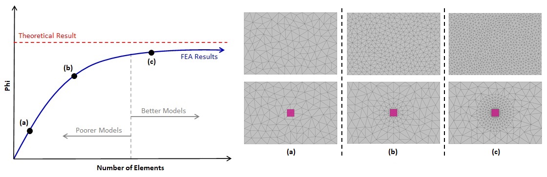
It is the user's responsibility to verify and validate the results obtained from ConcreteBending. The finite element method is approximate, and the accuracy of the solution depends on how fine the mesh is in the model (generally, a finer mesh produces more accurate results). A finite element mesh refers to the multiple plates that are used to model a single component (such as a slab). Mesh Refinement is the process of reanalyzing the model with successively finer and finer meshes and comparing the results between these different meshes. As the mesh is refined, the change in the solution becomes smaller and an asymptotic behavior of the solution starts to emerge as shown in the figure under Mesh Refinement Procedure below. Eventually, the changes to the solution will be small enough that engineering judgment can be used to determine that the model has converged.
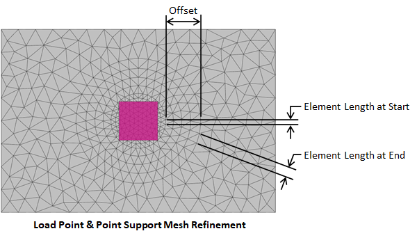
In ConcreteBending, mesh refinement is accomplished by reducing the Element Count in the . Furthermore, as shown in the image below, the mesh can be refined at Load Points and Point Supports by selecting the model object(s) and adjusting Mesh Refinement settings in the tab. In general, a finer mesh should be used in areas where there are large changes in stresses in the plates (e.g. load point locations that receive concentrated loads and point support locations where the support at a single node can create stress concentrations).
Note: Model results such as displacement, moment, shear, etc., which are represented as Phi in the graph below, will coverage at different rates. Therefore, it is important to ensure that the model has converged for the result of interests.
The bending part of the FEA plate element is based on the triangle formulation originally presented by Xu et. al.1 in 1992. This element accounts for transverse shear effects present in structures that might contain areas with thick plates, such as footings or thick floor slabs.
A Statics Check is performed for each load case analyzed in ConcreteBending. The total applied loads in each global direction is calculated and compared to the sum of all support reactions in the corresponding global directions. The applied loads are based on the deformed shape of the structure while the reactions are based on the structure's undeformed shape. If the loads and reaction are equal and opposite in magnitude, then the structure is in equilibrium. An imbalance indicates that the deflections are large enough to generate inaccurate results which might indicate that there is a modeling problem. ConcreteBending provides a warning if a significant imbalance is detected. If a warning is received, carefully review the model to ensure it is set up correctly and verify the results. The Statics Check is displayed on the tab or the Statics Check Information table can be added to the report.